| home |
|
|
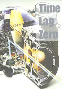 |
The OM-2 is a near identical twin to the OM-1 in appearance, structure and mechanical function. The addition of automatic exposure functions of the OM-2 extends the OM system quest for functionality to a new level. It is made possible by the TTL Direct (off-the-film) Light Measuring Method and the use of advanced electronic circuitry that is able to respond in microseconds. OM-2 was marketed in 1975. The research and development on the direct light measuring system was started around 1970. OM-2's automatic exposure determination is made from image-forming light reflected from the film. Two fast and sensitive Silicon Blue Cell (SBC) light sensors are located in the camera body, behind the lens, pointing back at the film plane. They go into action after the mirror is raised. They measure the light reflected off the film plane or the first shutter curtain. The curtain is printed with computer-generated random digital pattern which simulates the average reflectance of a broad variety of film surfaces.
A research on the reflectance of film surfaces was made. Films all over the world, not only from Japan, US, Europe but also from Eastern Europe, Russia and China etc, were analyzed. Except for special purpose film, the difference in reflectance between different films is surprisingly small. When sufficient light has reached the film, the electronic circuitry senses the information and instantly closes the shutter. If the light changes after the mirror is raised, or even half way through the exposure, the shutter speed will vary accordingly. With flash photography, the flash emission is monitored through the camera's taking lens by the camera's SBC light sensors. When the correct exposure has been made, the camera cuts off the flash via an electrical contact. TTL Direct (OTF) Light Measuring eliminates complicated exposure calculations associated with highly specialized fields of photography. For example, multiple flash photography and pinhole photography without a regular lens. |
|
 |
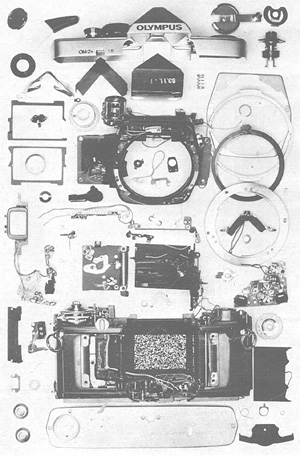
The control of the camera's electronic functions have been accomplished with surprisingly few electronic components. They are mostly located under the floor of the mirror box. These components include the integrated circuit devices, discrete resistor array for manual shutter-speed selection, whisker-like gold-plated switch elements, five potentiometers for adjusting all of the electronic functions, and two SBC, each in a tiny housing with a lens in front. ICs that can respond to weak electric current are developed. Sophisticated MOS and MSI components are used in the circuitry. They are hermetically sealed against moisture. In testing the electronic components in high humidity condition, sometimes the measuring equipment is damaged by the moisture. The circuit base is of specially treated, high purity alumina for exceptional resistance to moisture and leakage. The main switch is doubled with a sub-circuit, and the switch itself is made of special high conductivity alloys developed in the Apollo space program.
The uniquely constructed OM-2 is a masterpiece of mechanical compactness. A much-from-little design philosophy is carried throughout the camera. For the purpose of compactness and weight reduction, parts have been "skeletonized" (removal of material except where weakness would result). Certain sections of the main casting are quite thin. These sections are only visible after cover panels and various mechanism plates have been removed. These panels and plates, once securely fastened to the casting, serve as bracing and stiffening members. Gears and levers have thin profiles, but are heat-treated for toughness and wear-resistance. Small parts are tidily arranged and working co-operatively in minimal space. In a space just big enough for two shirt buttons, the shutter's gear-stack is poised on twin rows of ball bearings. This region typifies the entire camera : crowded but uncluttered. |
|
|
|
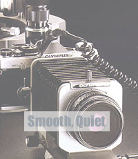
The mirror's action has undergone a series of impact-cushioning steps . One side of the mirror box contains most of the moving parts associated with the mirror and diaphragm motions. There are no less than six regions that have resilient pads to absorb the impact of moving parts coming to rest. The diaphragm-actuating arms in the lenses also have shock-absorbing cushions. A pneumatic cylinder, on the opposite side of the mirror box, dissipates the momentum of the mirror in both directions of its swing. The foam strips at the forward corners of the interchangeable focusing screen's frame absorb the final impact of the mirror's upward swing. Both the first (opening) and second (closing) shutter-curtain actions are effectively snubbed by separate braking systems. |
|
|
|
||
|
|
| OM
concept | OM-1
| OM-2
| OM-3, OM-4 | OM
lenses | OM
catalog | OM
adv |
OM
interview |