| Fluidic Thrust Vectoring for Low Observable Air Vehicles |
| Who am I? |
| Name: |
| Email: |

|
| Overview |
| Thrust vectoring is a technique whereby the orientation of the primary exhaust jet from a propulsive unit is varied in order to provide useful aircraft control moments. In a mechanical system, changes in nozzle geometry are used to generate the vectoring. On the other hand, fluidic thrust vectoring systems use a secondary air jet to control the direction of the primary jet. In contrast to mechanical systems, fluidic systems have the advantages of being lightweight, simple, of fixed geometry and can be implemented with minimal aircraft observability penalty. However, the main challenges with fluidic vectoring are in obtaining an effective, efficient system with reasonably linear control response. |


|
 |
 |
| Mason. M.S. and Crowther W.J., Fluidic Thrust Vectoring for Low Observable Aircraft, CEAS Aerospace Aerodynamics Conference, Session 13 No. 39, 10-12 June, Cambridge 2002 |
| Figure 1 Coflow fluidic thrust vectoring technique used in the present study |
| Fluidic thrust vectoring of a primary exhaust jet has been achieved here using the coflow technique, shown in figure 1. Curved reaction surfaces have been positioned downstream of the nozzle exit to which the jet may attach according to the Coanda effect. The side onto which the jet attaches is controlled by tangential injection of a secondary jet of air upstream of the surfaces. The resulting thrust vector force generated on the reaction surface can then be used to provide useful moments for aircraft control. |
| Results Summary |
| Experimental Force Data |
| Figure 2 Idealised control response curve A - Dead zone, B - Control zone, C - Saturation zone |
| a) Non-vectored case |
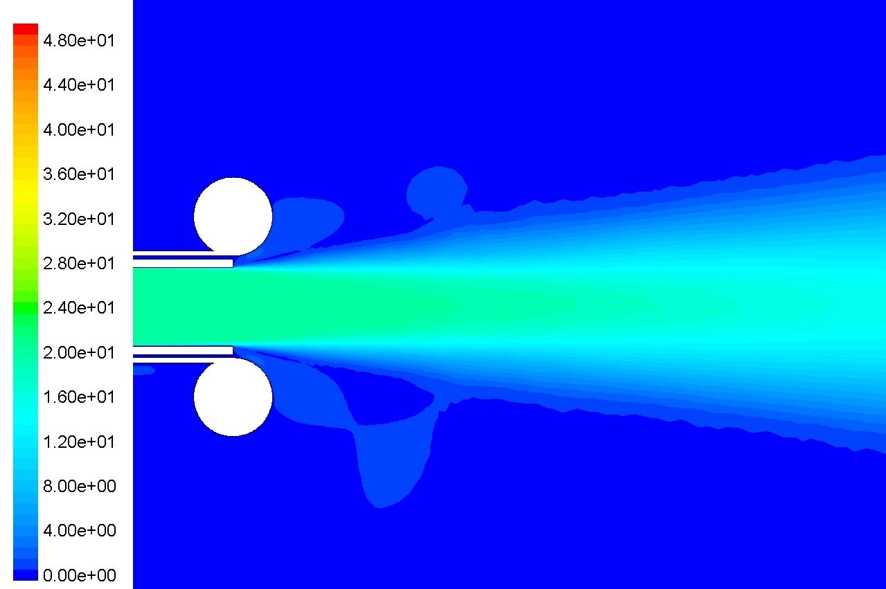
| b) Vectored Case |
| Figure 3 Contours coloured by velocity magnitude |
| Publications: |
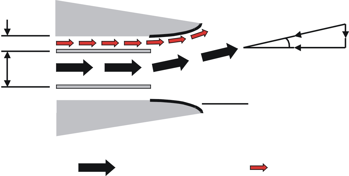 |
| Primary Jet |
| Secondary Jet |
| Reaction Surface, R |
| hs |
| hp |
| Fz |
| Fo |
| Fx |
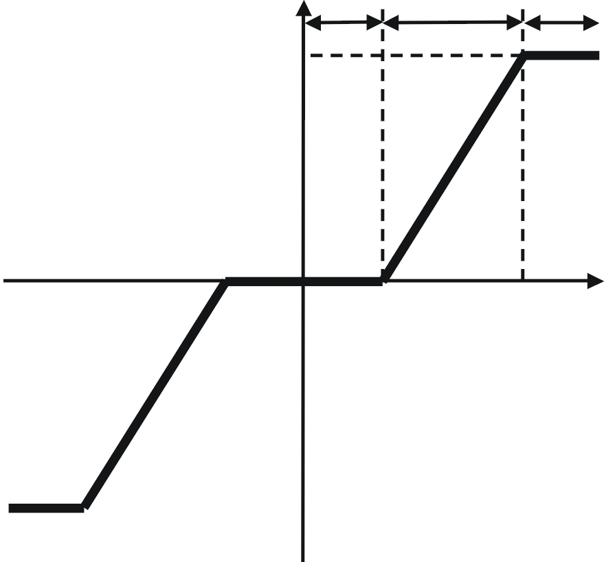 |
| A |
| B |
| C |
| Cmu |
| Cz |
| Computational Investigation |
| Cz = |
| Thrust Vector Force |
| Thrust Force of Non-vectored Primary Jet |
| Cmu = |
| Secondary Jet Momentum Flow Rate |
| Primary Jet Momentum Flow Rate |
| hs/hp = 0.04, R/hp = 0.04 Cmu = 0.12, Cz = 0.37 |
| hs/hp = 0.04, R/hp = 0.04 Cmu = 0, Cz = 0 |
| Last updated: 27/06/2003 |