©2000+ EngineeRunner
Inc. About | Contact
WIND LOAD DESIGN ANALYSIS: ASCE 7-98
Loren Pittack and Julio de Blas (Partnership)
CAE614 Structural Dynamics
University of Miami College of Engineering: Civil, Architectural, and Environmental Engineering Dept
Professor Fahmy
December 12, 2000
 Simple
concepts have frequently been used in estimating live loads for structural
design. Now, however, live loads on buildings, such as wind, snow, earthquake
and floor loads, are receiving increased attention to match more accurate
structural analyses that are possible. Wind loads have become particularly
significant because of increasing number of high-rise buildings. Other
factors have also contributed to importance of wind in design: lightweight
low-slope roofs, curtain wall construction and appearance of special structures
having "aerodynamic shapes." Some tall buildings that extend into regions
of high wind velocity have swayed excessively in strong winds. Wind forces
have blown off improperly anchored lightweight roofs, and roofing materials
have been lifted by high local suctions and eventually peeled from large
areas of roofs. These and many other problems have emphasized the importance
of a clearer understanding of wind and its effects. With the old simplified
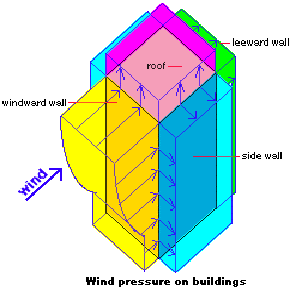
approach, merely a uniform lateral pressure on windward side of a building
and suction on leeward wall often represented total effect of wind. Crossly
simplified rules were also used to calculate pressures or suctions on roofs.
Only horizontal shear and overturning moment were calculated. For low or
medium height buildings, such simple methods may have been reasonably satisfactory,
but for tall buildings, the greater importance of wind loading calls for
more accuracy. Wind is not constant either with height or with time, is
not uniform over the side of a building, and does not always cause positive
pressure. In fact, wind is a very complicated phenomenon; it is air in
turbulent flow, which means that motion of individual air particles is
so erratic that in studying wind, one ought to be concerned with statistical
distributions of speeds and directions rather than with simple averages
or fixed physical quantities.
Simple
concepts have frequently been used in estimating live loads for structural
design. Now, however, live loads on buildings, such as wind, snow, earthquake
and floor loads, are receiving increased attention to match more accurate
structural analyses that are possible. Wind loads have become particularly
significant because of increasing number of high-rise buildings. Other
factors have also contributed to importance of wind in design: lightweight
low-slope roofs, curtain wall construction and appearance of special structures
having "aerodynamic shapes." Some tall buildings that extend into regions
of high wind velocity have swayed excessively in strong winds. Wind forces
have blown off improperly anchored lightweight roofs, and roofing materials
have been lifted by high local suctions and eventually peeled from large
areas of roofs. These and many other problems have emphasized the importance
of a clearer understanding of wind and its effects. With the old simplified
approach, merely a uniform lateral pressure on windward side of a building
and suction on leeward wall often represented total effect of wind. Crossly
simplified rules were also used to calculate pressures or suctions on roofs.
Only horizontal shear and overturning moment were calculated. For low or
medium height buildings, such simple methods may have been reasonably satisfactory,
but for tall buildings, the greater importance of wind loading calls for
more accuracy. Wind is not constant either with height or with time, is
not uniform over the side of a building, and does not always cause positive
pressure. In fact, wind is a very complicated phenomenon; it is air in
turbulent flow, which means that motion of individual air particles is
so erratic that in studying wind, one ought to be concerned with statistical
distributions of speeds and directions rather than with simple averages
or fixed physical quantities.
Architects and engineers are concerned with and responsible for not
only structural design, but also the choice of exterior cladding materials
and components, operation of mechanical services such as heating and ventilating
equipment, and with details of openings to limit infiltration. Wind has
important effects on each of these aspects of design; one might even conclude
that of the manifestations of nature with which the architect has to contend,
apart from gravity, the effects of wind are ubiquitous.
Development of Wind
Wind usually refers to movement of air parallel to the earth's surface.
Driving forces for such movements are pressure differences caused by unequal
heating of the air. For a steady wind, however, direction of flow does
not follow the steepest pressure gradient from a "high" to, a low" as one
might expect. In fact, direction of flow is more nearly parallel to the
isobars (lines connecting points of equal pressure) rather than perpendicular
to them. This is because every object moving across the earth's surface
deflects to the right in the northern hemisphere (to the left in the southern)
because of rotation of earth. This deviating effect, called the Coriolis
force, is small and is usually disregarded except in the atmosphere and
ocean. Pressure gradient causing wind, however, is also small. Normally,
wind requires several hours to develop, and although flow begins perpendicular
to the isobars, it gradually deflects to the right as time passes, so that
when a steady state is attained, wind blows more nearly parallel to the
isobars. The Coriolis force and frictional drag force then balance the
pressure gradient, plus or minus centrifugal force if path happens to curve.
Velocity Profile
The roughness of the earth's surface, which causes drag on wind, converts
some of wind's energy into mechanical turbulence. Since turbulence generates
at the surface, surface wind speed is much less than wind speed at higher
levels. Turbulence includes vertical as well as horizontal air movement
and hence the effect of surface frictional drag is propagated upwards.
Mechanical turbulence and effect of frictional drag gradually decrease
with height and at gradient level (around 1000 to 2000 feet) the frictional
effect is negligible. Pressure gradient at this level balance by the Coriolis
force (and possibly centrifugal force), and the wind blows almost parallel
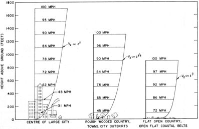
to the isobars. For strong winds, the shape of the vertical profile of
wind speed depends mainly on degree of roughness of surface, which means
over-all drag effect of buildings, trees and any other projections that
impede flow of wind at the surface. Three typical velocity profiles are
shown in Fig. 1, where the effect of variable surface roughness on mean
wind speeds is shown for an arbitrarily selected gradient wind of 100mph.
Velocity profiles have been determined by fitting curves to observed mind
speeds at several levels. It is convenient and sufficiently accurate to
describe these profiles by a power law of the form: vh =
vr*(h/hr)k, where vh
is mean wind speed at height h above ground, vr
is the mean speed at reference height hr, above ground;
k
is the exponent for best-fitting curve. A reference height of 10 meters
or about 30ft is internationally recommended as the standard and anemometers
are usually mounted as close to this height as is practical. Exponents
for mean wind speeds vary from about 1/7 for flat open country to about
½ for centers of large cities.
Figure 1 - Mean velocity profiles over terrain with 3 different
roughness characteristics for gradient wind of 100mph. Courtesy Meteorological
Division, Dept of Transport
 Turbulence
in Surface Winds
Turbulence
in Surface Winds
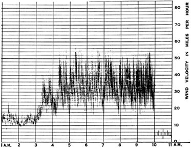
Velocity profile (Figure 1) describes only one aspect of wind at lower
levels. Superimposed on mean speed are gusts and lulls, which are deviations
above and below the mean. These gusts have a random distribution over a
wide range of frequencies and amplitudes, in both time and space. Figure
2 shows clearly the unsteady nature of wind speed measured by an anemometer.
Gusts are frequently the result of the introduction of fast moving parcels
of air from higher levels into slower moving strata of air. This mixing
or turbulence is produced by surface roughness and thermal instability.
In such cases dynamic instability of flow may result when eddies separate
first from one side and then form. Turbulence caused by surface roughness
is similar to the turbulent boundary layer flow at the walls of pipes.
Flow near surface encounters small obstacles that change wind speed and
introduce random vertical and horizontal velocity components at right angles
to main direction of flow. Turbulence generated by obstacles may persist
downwind from projections as much as 100 times their height. Large scale
topographical features are not included in the above-mentioned surface
roughness. They can influence the flow, so they are given special consideration
in design. For instance, wind is usually much stronger over the brow of
a hill or ridge because flow lines converge over the obstructing feature
and to pass the same quantity of air a higher speed is required. Large
valleys often have a strong funnelling effect that increases wind speed
along the axis of the valley. Thermal stability of air has a considerable
effect on the intensity of turbulence. Cold surface air tends to damp out
mechanical turbulence; heated surface air tends to rise and to increase
turbulence. When wind is strong, air near the surface becomes thoroughly
mixed and thermal stability becomes neutral. Under these conditions, temperature
differences neither damp out nor increase mechanical turbulence caused
by surface roughness. Figure 2 - Typical pressure tube anemometer
record.
 Dynamic
effects
Dynamic
effects
Every structure has a natural frequencyof vibration, and should dynamic
loading occur at or near it, structural damage out of all proportion to
size of load may result. For example, bridges capable of carrying far greater
loads than the weight of a company of soldiers have been known to break
down under dynamic loading of men marching over them in step. Similarly,
certain periodic gusts within the wide spectrum of gustiness in wind may
find resonance with natural vibration frequency of a building, and although
the total force caused by that particular gust frequency would be much
less than the static design load for the building, dangerous oscillations
may be set up. This applies not only to the structure as a whole, but also
to components such as curtain wall panels and sheets of glass. A second
dynamic effect is caused by instability of flow around certain structures.
Long narrow structures such as smoke stacks, light standards and suspension
bridges are particularly susceptible to this sort of loading the other
side of the object, causing an alternating pattern of eddies to form in
its wake. A side thrust is thus exerted on the object similar to the lift
on an aerofoil, and since this thrust alternates in direction, a vibration
may result. Side-to-side wobbling effect of a straight stick pulled through
water is an example of this phenomenon. As research gradually provides
a better understanding of the structure of wind and the complex interactions
between wind and buildings, one can look forward to greater economy in
the use of building materials through greater precision in estimating static
load; and to greater safety because of the inclusion of dynamic load in
design.
Minimum Wind Design Loads for Building & Other Structures
ASCE Standard A7-98, Minimum Design Loads for Buildings and Other Structures
(A7 Standard) provides a basis for determining wind loads and other loads
on structures in the United States. All model-building codes include this
standard as a reference and the new International Building Code has adopted
the A7 Standard as the recommended design method. Evaluation of wind loads
can be a very complicated process and the A7 Standard has provided the
best information currently available for dealing with these problems for
rigid structures and a limited class of flexible structures. Unfortunately,
complication of wind loading also can lead to a relatively complicated
procedure for code-based evaluation of wind loads. A full evaluation of
the structure, parts and portion loadings for even a relatively simple
structure can lead to lengthy and tedious calculations using the A7 Standard.
The Wind Loads on Structures program recently released by the Standards
Design Group removes much of the tedious computation for manual analysis
and reduces evaluation of A7-98 to relatively simple steps. All buildings
and other structures must be design to resist environmental loads. This
is a wind load. Design wind loads can determined using 3 procedures: Simplified
procedure, Analytical procedure and Wind tunnel procedure. There are definitions
one must know in order to understand procedures of determining wind loads.
These definitions are based on a dynamic point of view:
Flexible building or structure: A building or other structure
is considered flexible if it contains a significant dynamic response. Resonant
response depends on the gust structure contained in the approaching wind,
on wind loading pressures generated by the wind flow about the building,
and on dynamic properties of the building or structure. Gust energy in
wind is smaller at frequencies about 1 Hz; therefore resonant response
of most buildings and structures with lowest natural frequency above 1
Hz will be sufficiently small that resonant response can often be ignored.
When buildings or other structures have a height exceeding 4 times the
least horizontal dimension or when there is reason to believe that the
natural frequency is less than 1 Hz (natural period greater than 1sec.),
the natural frequency should be investigated.
Rigid building or structure: Building or other structure whose
fundamental frequency is greater or equal than 1 Hz. A general guidance
is that the most rigid buildings and structures have height to minimum
width less than 4.
Design Force, F: Equivalent static force is used in determination
of wind loads for open buildings and other structures.
Design pressure, P: Equivalent static pressure to be
used in the determination of wind loads for buildings.
Main wind-force resisting system: An assemblage of structural
elements that provide stability and support for overall structure.
Wind Load Design Analytical Procedure
Gust effect factor G
For rigid structures, gust effect factor shall be taken as 0.85 or
calculated by: G = 0.925*[(1+1.7gQIzQ)/(1+1.7gvIz)].
Iz = c(33/ )1/6,
where Iz is the intensity of turbulence at height (equivalent
height of structure defined as 0.6h); gQ and gv
shall be taken as 3.4. Refer to ASCE 7-98 for values. Background
response Q = SQRT(1/[1+0.63*((B+h)/Lz)0.63]),
where Lz = l(/33)^
)1/6,
where Iz is the intensity of turbulence at height (equivalent
height of structure defined as 0.6h); gQ and gv
shall be taken as 3.4. Refer to ASCE 7-98 for values. Background
response Q = SQRT(1/[1+0.63*((B+h)/Lz)0.63]),
where Lz = l(/33)^
Flexible or Dynamically Sensitive Structures
For dynamically sensitive structures, gust factor shall be calculated
by: Gf = 0.925*[(1+1.7*Iz*SQRT(gQ2Q2+gR2R2))/(1+1.7gvIz)]
gQ and gv shall be taken as is
given by: gR = SQRT(2*ln(3600n1))+[0.577/SQRT(2*ln(3600n1))],
where n1 = Building natural frequency (Hz). The resonant
response factor = R = SQRT(RnRhRb(0.53+0.47Rl)/B),
where Rn = 7.47*N1/(1+10.3N1)5/3.
Reduced the frequency, N1 = n1Lz/ .
Rl = 1/n - (1 - e-2n)/(2n2), for n
> 0. q = qz = 1, for n = 0, where subscript
l
shall be taken as h, B and L respectively:
q = qz setting n = 4.6n1h/
.
Rl = 1/n - (1 - e-2n)/(2n2), for n
> 0. q = qz = 1, for n = 0, where subscript
l
shall be taken as h, B and L respectively:
q = qz setting n = 4.6n1h/
q = qz setting n = 4.6n1B/
q = qz setting n = 4.6n1L/
B = Damping ratio (% of critical damping). Mean hourly wind speed
(ft/s), =  (/33)^
 *V(88/60),
whereandare
constants.
*V(88/60),
whereandare
constants.
Velocity pressure
Velocity pressure, qz, evaluated at height z
shall be calculated using following equation: qz = 0.00256KzKztKdV2I
(psf) where Kd = wind directionality factor,
Kz
= velocity pressure exposure coefficient,
Kzt = topographic
factor and qh = velocity pressure at mean roof height
h.
Pressure and Force Coefficients
Main Force Resisting System & Rigid buildings of all heights
Design wind pressures for main wind force resisting system of buildings
of all heights shall be determined by following equation: p = qGCp
- qi(GCpi) (pssf), where q = qz
for windward walls. q = qh for leeward walls, side walls
and roofs. qi = qh for windward walls, side
walls, leeward walls and roofs of enclosed buildings. qi
= qz for positive internal pressure evaluation in partially
enclosed buildings.
G = Gust effect factor. Cp
= External pressure coefficient.
(GCpi) = Internal pressure
coefficient.
Low Rise Buildings
Design wind pressures for main wind force resisting system of low-rise
buildings shall be determined using equation: p = qh[(GCpf)
- (GCpi)] (psf), where (GCpf) = External
pressure coefficient.
Flexible Buildings
Design wind pressures for main wind force resisting system of flexible
buildings shall be determined from following equation: p = qGfCp
- qi(GCpi) (pssf)
Wind Loads Commentary
Maximum Along-Wind Displacement
Maximum along-wind displacement as a function of height above ground
surface is: Xmax(z) =  p*B*h*Cfx
 2/[2m1(2*PI*n1)2]*KG,
where fundamental model shape = =
(z/h)^
2/[2m1(2*PI*n1)2]*KG,
where fundamental model shape = =
(z/h)^ . =
Mode exponent. p = Air density. Cfx = Mean along-wind
force coefficient. Modal mass =
. =
Mode exponent. p = Air density. Cfx = Mean along-wind
force coefficient. Modal mass = 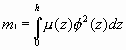 ,
where µ(z) = Mass per unit height. K = 1.65^â/(â++1). (3-sec.
gust speed) =
,
where µ(z) = Mass per unit height. K = 1.65^â/(â++1). (3-sec.
gust speed) =  V(z/33)^â,
where V is 3-sec. gust speed in Exposure C at reference height;
and â are terrain exposure constants given in tables.
V(z/33)^â,
where V is 3-sec. gust speed in Exposure C at reference height;
and â are terrain exposure constants given in tables.
RMS Along-Wind Acceleration
RMS Along-wind acceleration as a function of height above ground surface
is: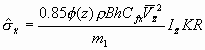 .
.
Maximum Along-Wind Acceleration
Maximum along-wind acceleration as a function of height above ground
surface is: .
gx
= SQRT(2*ln(n1T)) + 0.5772/SQRT(2*ln(n1T)), where
T
= time length over which minimum acceleration is computed, usually taken
to be 3600sec. to represent 1hr.
.
gx
= SQRT(2*ln(n1T)) + 0.5772/SQRT(2*ln(n1T)), where
T
= time length over which minimum acceleration is computed, usually taken
to be 3600sec. to represent 1hr.