 Dynamite
Canyon Tramway Reversing Loops
Dynamite
Canyon Tramway Reversing LoopsDynamite
Canyon Tramway Reversing Loops
Reversing loops, almost every modeller has thought about using them at one time or another. Those with electrical skills can get them to work, but often at the expense of having an operator/train driver/guest modeller navigate their way through extra switches/control panels/throttles just to get their train around the loop. Others attack the problem with high $$$ electronics. For the rest of us, a simple solution, which doesn't require the operator to do or learn anything extra when running their train, and costs minimum $$$, would be great.
Here's the DCT solution.
Lets start with a few known facts and limitations.
1: This solution assumes that you wish to use the reversing loop purely for turning trains around, and thus, you will not mind that your trains must always navigate the loop in the same direction.
2: This solution requires some knowledge of your track and wheel details, (specifically in relation to gauge and flangeways), as it involves modifying a PECO Insulfrog or similar plastic frog point, (sorry, metal frog points need not apply).
3: This solution has been tested and optimized for regular DC throttles. (I can run Dynamite Canyon directly off a 9VDC battery if need be). DCC systems were not considered when designing it. Most DCC systems already have facilities for handling reversing loops and suchlike, (dual "switchable" boosters etc). If you are running a DCC system, or are considering obtaining one, check the respective manufacturer for details on reverse loop wiring.
OK, having set out the rules, Keep the following detail in mind...
...the NMRA standard says that where a locomotive is moving "Forward", the Right hand rail must be + polarity...
This small but significant detail means that we can accurately, and reliably, make a train go in a desired direction, by ensuring that "Forward" = Right hand rail is + volts.
Here's another basic detail to keep in mind,
...a train approaching a track point/switch, everything else being equal, will want to take the straight route...
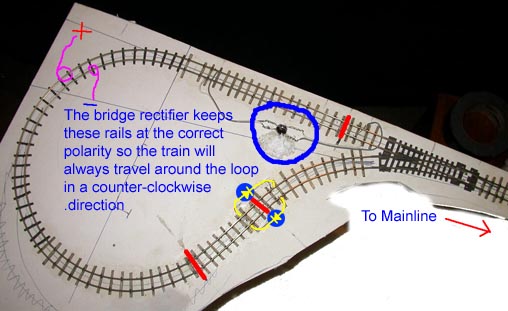
Now check the pic of the "top loop" on the DCT layout.
 OK,
a quick legend.
OK,
a quick legend.
The RED
lines show the location of isolation gaps which have been
cut in both rails.
The Yellow
things backed with blue dots represent regular
1N4001 silicon diodes.
The Black
thing in the blue circle is a bridge rectifier. In this example, it is talking
a track feed from the mainline rails, (at right of the bridge), and are feeding
constant polarity track power to the loop block, (exiting the bridge to the
left).
OK, follow me step by step around the loop.
1: Mainline train heads left on
Mainline (At right of pic above)
2: Due to point modification, train takes the "straight
route" through the point, and heads into the loop, (Top side of loop in
pic above).
3: Train passes over 1st isolation rail gap.
Now, between the point and the rail gaps, (top gaps on pic above), the train is still getting power from the mainline, via the points. If the driver were to stop the train before crossing the gap, (if they stayed on the RIGHT side of the gaps), the train could be backed out of the loop, because it's direction polarity is still under the direct control of the Mainline throttle direction switch.
 As
soon as the train passes over the gaps however, (passes over the gap from Right
to Left), it has entered the "loop block". This stretch of track receives
it's power from the mainline, via the bridge rectifier. The bridge rectifier
keeps this section of track powered with the +
polarity to the "right" of the train, hence the train will continue
to proceed around the loop in a Counter-clockwise direction. (Remember
"Detail #1"?).
As
soon as the train passes over the gaps however, (passes over the gap from Right
to Left), it has entered the "loop block". This stretch of track receives
it's power from the mainline, via the bridge rectifier. The bridge rectifier
keeps this section of track powered with the +
polarity to the "right" of the train, hence the train will continue
to proceed around the loop in a Counter-clockwise direction. (Remember
"Detail #1"?).
At right is a quick wiring schematic for bridge rectifiers. DCT uses WO-4 4amp bridges, which should handle enough current for most locomotives up to On3.
4: Train now proceeds, with bridge rectifier controlling the direction, around loop (Counter-clockwise in above pic).
5: Train passes over 2nd rail gap, (bottom centre of pic).
Here's where the real issues start, and many modellers are convinced that they need extra electronics. If you have been following the steps on the pic above, and you have been keeping track of which rail is what polarity, you will soon realize that the train cannot return back onto the mainline without causing a short circuit.
Look
at the pic again. With the train having navigated the loop, it has now crossed
onto another short "block" section. In practical terms, this section
need only really be as long as the longest loco you envisage running around
the loop. This short block gets its power not from the bridge rectifier, but
from the mainline, via 2 inline or "series connected" diodes, (shown
in yellow on the pic).
In basic terms, diodes will let power pass through them in one direction, (or at one polarity), but not the other. By using the diodes to power this short section, we can effectively work out if the mainline throttle direction is still set to head "into" the loop, or has been reversed, ready to accept a train exiting the loop. If the throttle is still set to "inbound", the diodes will stop power passing to the short block, and the loco will stop. How do you know which way to wire the diodes? Remember "Detail #1"? Wire the diodes so that the "triangle symbol" has the triangle head pointing from + to - for the desired direction of travel.
6: If/when the throttle direction switch is changed to accept the train from the loop, the diodes will let the correct polarity mainline power through, and the train will continue over the final "rail gap", out of the loop, and back onto the mainline, in the opposite direction.
That's all there is too it. No mention of, or need for, detectors, point motors, extra switches, or anything complicated. Your operator drives their train "into the loop", it turns itself around, if the operator changes their throttle direction switch while the train is navigating the loop, it will continue without stopping or reversing, and will exit the loop, back onto the mainline. If the operator does not change their throttle direction switch, the train will stop automatically on the "short block", and will wait there until they do.
BTW, there is a slight voltage drop across the bridge rectifier and diode pair, around 1.2volts. If your train heads into the loop at a "medium cruising speed", it will slow slightly as it negotiates the loop. If you are building the reversing loop for the purposes of turning a train, you will probably have used whatever your minimum radius is, so it takes up as small a space as possible. Being a tight curve, having the train slow slightly is actually a small bonus of this circuit ;-)
That takes care of the electrics. For info on how to modify a PECO Insulfrog point so that a train will "always go straight", click here.
 BTW,
as a bonus, if you're clever, you can adjust the length of the "loop block"
and "short block" so that the straight leg portion of the loop can
be used in regular operations. See the pic at left for a suggestion on how to
do it. Note that because you have modified the point to
always "run straight", it acts effectively like a piece of straight
track. Hence, you can run in true "Point-to-Point" mode, by entering
the loop, switching the district, then leaving the loop the way you came, or
run around the loop, and return to the mainline using the "reverse loop".
BTW,
as a bonus, if you're clever, you can adjust the length of the "loop block"
and "short block" so that the straight leg portion of the loop can
be used in regular operations. See the pic at left for a suggestion on how to
do it. Note that because you have modified the point to
always "run straight", it acts effectively like a piece of straight
track. Hence, you can run in true "Point-to-Point" mode, by entering
the loop, switching the district, then leaving the loop the way you came, or
run around the loop, and return to the mainline using the "reverse loop".