 Dynamite
Canyon Tramway "Always Straight" Points
Dynamite
Canyon Tramway "Always Straight" PointsDynamite
Canyon Tramway "Always Straight" Points
I owe the kernel of this idea to legendary Australian Narrow Gauge Modeller, Gerry Hopkins. His last NG exhibition layout featured handlaid dual gauge points that always allowed a train to "go straight", thus allowing automated multi train passing loop operations and suchlike, with minimal additional active electronics. I just found a way to simulate Gerry's idea, using off the shelf PECO Insulfrog points.
One of the key elements of the DCT "automatic reversing loop" is a point which always forces a train approaching it to take the straight path. There are a few different ways to achieve this, but one of the DCT criteria was that the point have no moving parts.
 Here's
how it was done.
Here's
how it was done.
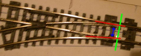
1: The green line represents where the original throwrod was. It was simply removed, along with the PECO over-centre spring. This allows each switch rail to swing independently.
2: The blue arrow indicates where the switchrails have been pushed hard up against the nearest stock rail, and soldered to it. This may appear to require the modeller to have 3 or more hands available, but if you tin the rails first, and use a pair of "reverse" or "self clamping" metal tweezers to hold the switch and stock rails together, your 2 regular hands are free to manipulate the soldering iron and solder ;-) This PECO N scale "setrack" point was done with a 40watt electronics soldering iron. Make sure that the switchrails are clamped vertically inline with the stockrails, they may attempt to creep "up" the inside of the stockrail, and end up soldered slightly "proud" of the top running surface of the stockrail.
NB, this does not have to be a immaculate solder joint, in fact a little extra solder pooled in-between the switch and stock rails will be beneficial.
3: Having soldered the stock and switch rails together, you will quickly realize that it is now impossible for any piece of rollingstock to use the point. The solution is shown by the red lines. These indicate the areas where you will need to saw/file/carve a "flangeway". through the switchrail and pooled solder. Razor saw, Dremel tool with cutoff disk, narrow file, all will do the job. Just remember that the faster the tool works, the more certain you have to be that you are cutting the right part of the rail away!
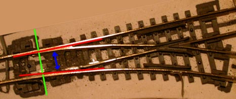
NB, there are 2 basic approaches to carving a working set of flangeways.
One is to use an appropriate NMRA trackgauge
or similar, and carve the flangeways relative to the appropriate stock rail.
The 2nd is to connect a length of flextrack to each leg of the point, grab a piece of rollingstock, and start cutting the "straight" flangeway, (the top one in the pic above). Every so often, roll the car from the toe to the heel end of the point, (from right to left on the point shown above). When the car smoothly passes through the "straight route" without "humping" over the curved switchrail, Stop Cutting! Now start cutting the "curved" flangeway, occasionally rolling the test rollingstock from the heel to the toe end of the point, along the curved route. Again, when the car rolls through the point without "humping" over the straight switchrail, Stop Cutting!
Having cut the flangeways, check that the top running surface of the rails is smooth, (run your test car through the point again a few more times, I know you will want to, esp if the point is working properly ;-) ). If not, give the solder joint top areas a few swipes with a small file to smooth them off. Now roll that test car to check the point again.
 Here
is the "Bottom Loop" point on DCT. Note that between the 2 loops,
DCT provides a working example of both a "left handed" and "right
handed" loop. Both use the same techniques and electronics, and both work
flawlessly.
Here
is the "Bottom Loop" point on DCT. Note that between the 2 loops,
DCT provides a working example of both a "left handed" and "right
handed" loop. Both use the same techniques and electronics, and both work
flawlessly.
A quick note about point selection. This technique will only work with PECO "Insulfrog" or other plastic frog points that have a "power routing" feature. As soon as the switch rails are soldered to the stock rails, they become electrically joined. With a metal frog point, this would mean an inherent short circuit. So, for the purposes of this project, "Electrofrog" or metal frog equipped points need not apply.
One or 2 modellers have questioned the butchering of a completely good and serviceable point for this project. "Why not just remove the over-centre spring, and add a spring to the "curved route" side of the throwrod, thus turning the point into a "sprung switch"?" Well, apart from the intrigue of a point with absolutely no moving parts, it was discovered that some plastic wheeled and lightweight rollingstock, esp in the smaller scales, simply did not have the force to push the sprung switchrails aside when exiting the loop. Making the spring weaker meant that the point did not reliably return to the "straight" position everytime, and for this project, reliability and predictability were high on the list of specifications.
To learn how to wire up the DCT "Automatic Reversing Loop", click here.
To return to the DCT Homepage, click here.