 Broughton
Creek Structures
Broughton
Creek Structures Broughton
Creek Structures
Here is a detailed overview of the structures of Broughton Creek. Apologies for it's length and load time. Enjoy.
 There is really only one man
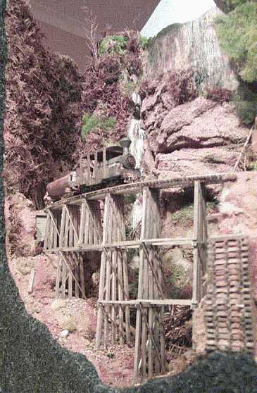
made structure in the Broughton Creek scene, but it's a BIG one. The trestle
across Broughton Creek was scratchbuilt to a general prototype design sketched
in a exercise book. This was very much a case of building a bridge to fit a
space. Two quick tips from building structures, especially big ones like trestles
or large buildings:
There is really only one man
made structure in the Broughton Creek scene, but it's a BIG one. The trestle
across Broughton Creek was scratchbuilt to a general prototype design sketched
in a exercise book. This was very much a case of building a bridge to fit a
space. Two quick tips from building structures, especially big ones like trestles
or large buildings:
Tip 1: Make
3 copies of your plans. The original goes into your layout file for future reference,
Copy 1 goes next to the work bench for visual reference, Copy 2 is on the workbench
for direct measurement, and Copy 3 goes to Tip 2.
Tip 2: Build
on glass. Obtain a sheet of glass, (offcuts from glaziers are cheap, but get
the glazier to smooth ALL the edges, they can be SHARP!), and place the 3rd
copy of your plan under it. Building on glass will ensure all of your assemblies
are flat, and glue such as CA won't permanently stick your model to the smooth
surface.
Due to the track geometry on the end of the layout, this trestle was built with a straight centre section, and curves at each end. To form this compound curve deck, the "straight deck" above was cut into sections with angles at each end of each 14' length. Three 14' sections formed the Broughton Vale end, (nearest to the camera in this shot), two 14' sections formed the Woodhill Cutting end, and these two curves were linked with a 28' straight section in the centre.
The resulting deck was both strengthened and detailed by the addition of styrene "Joint plates" on either side of each joint. They are the rusted steel plates with bolts visible above each upright bent. The slow task of gluing individual sleepers, cut from scale wood, to the bridge deck was then completed. This included installation of two extended sleepers to accommodate a track gang refuge on the inside of the curve about half way across.
The track for this section had already been temporarily laid with N scale flextrack to check the minimum curve radii and other such operational considerations. Before it was taken up to allow the creek to be carved out of the layouts foam base, the tops of the rails were soldered together with scraps of rail. This formed a sort of curved nickel silver "ladder". When the deck sleepers were all dry, the plastic sleepers were stripped from the flextrack "ladder", and the "ladder" was spiked and glued to the deck. Once all was in place, the scrap rail was de-soldered from the tops of the running rails, now safely mounted on the trestle deck. Result? A compound curved trestle deck, with individually laid rail which is perfectly in gauge and in alignment.
With just about everything above the deck done, it was time to tackle the bottom bits. From one full size plan of the tallest bent, five standard bents and one span bent were patterned. To get the varying heights, six "baselines" were drawn across the plan where the bottom of the bent had to end up. The bents were then built from the top down to the appropriate line. The bents are constructed from 12" X 12" scale wood with 4" X 4" cross bracing. These sizes are not based on any particular prototype measurements, just approximations based on the overall proportion of the structure, and what was in the wood scrap box.
When all of the bents were completed, the major assembly began. This step was taken slowly, because the final appearance of the bridge was at stake. Turning the deck assembly upside down, and working from the centre bent out, two engineers squares were used to support each bent while they were glued in place. Placing the bents was easy, because each bent had to go directly above, (or below, depending on which way you look at it), each span joint. Once finished, the trestle looked something like an oversized wooden hair comb. The bents were very fragile at this point, because they were only supported by the joint with the deck.
The final step was to start from the centre, both along the length and width of the trestle, and carefully glue each individual brace in between each bent. This step was time consuming and took a lot of patience, but the end results were worth the effort.