Dr.Seal Home Horizons Stratigraphy
|
||||||||
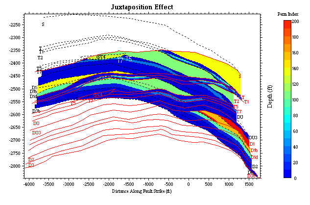
| Permeability index across the fault after juxtaposition effect is considered only. Horizon lines are superposed to help identifying horizon intervals. Note that the channel sand (@T4) on the down-thrown side has been totally sealed off by the up-thrown D2 and D3 shales. The channel sand on the up-thrown side, however, is in contact with a down-thrown side S sand, which does not seal this channel sand. Two high permeability areas on the right (in yellow, red and brown) are caused by juxtapositions of sand intervals against themselve due to limited fault throw near the fault tip. The relatively high permeability area in the middle left (yellow) will change when shale smear effect is considered in next picture. | ||||||||
|
||||||||
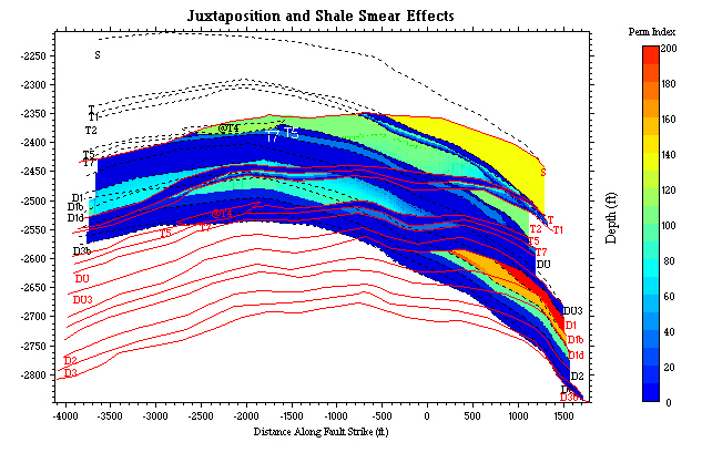
| This image shows effects of both juxtaposition and shale smear. Horizon lines are superposed to help identifying horizon intervals. The shale smear effect is calculated using shale gouge ratio algorithm. Note that the risky area noted in previous image (middle-left of the image) now has lower permeability index and thus is relatively safe. The high permeability areas on the right remain and should not be a concern because they are caused by the same sand juxtaposition at the fault tip. The only remaining high risky area is the up-thrown channel sand (@T4), which has the highest permeability index in the remaining area. Oil/water contacts and production records support the conclusion from this analysis that the fault leaks oil throw the up-throw channel part, which caused depletion of a large amount of oil reserve. Dr.Seal Home Horizons Stratigraphy |
||||||||