DC RX Module
A few months ago, I designed a PCB for this little module, and then didn't do much with it. I did supply a couple of PCBs to someone for use with a DSP-based receiver. I subsequently revisited the project and decided to revamp the PCB, tidying up the layout and making construction easier.
It's intended as a component in a high-performance receiver, and was designed for maximum flexibility, in that it only includes the mixer (an MCL +7 dBm TUF-1), audio diplexer and low-noise AF pre-amplifier. Input filtering, oscillator, AF filter etc. are all external.
It may be used in many receiver configurations: as a simple DC receiver, binaural receiver, phasing receiver, etc. It's ideal for use with a DSP system. Since the TUF-1 mixer is specified up to 500 MHz, the module will be suitable for 70 cm. By swapping over the RF and IF connections to the mixer (a couple of track cuts and two pieces of wire), LF and VLF reception is feasible.
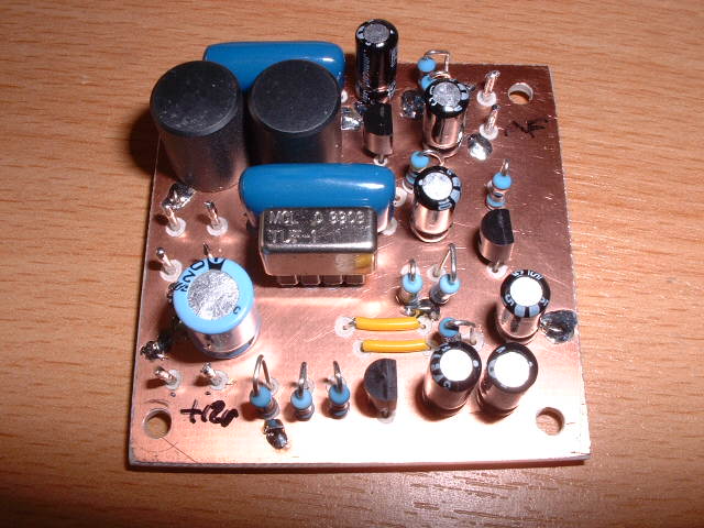
Above is a picture of the assembled module, which is 2" square. To save space, the resistors are mounted vertically. I've used some SIL turned-pin socket strip for the TUF-1 mixer. It also makes a convenient tester for these devices. The PCB is made from double-sided material, with a top ground plane, and tracks on the bottom. It only needs three wire links.All connections are via terminal pins.
The circuit (above) is based on KK7B's designs, and uses a TUF-1 mixer (+7 dBm oscillator input level), followed by a simple audio diplexer using two Toko shielded inductors and two metallised polyester capacitors which ensures that the mixer always sees 50 ohms on the output. The audio signal is then amplified in a low-noise pre-amplifier with 50 ohms input impedance. The amplifier circuit is taken from Rick's binaural receiver in the current Handbook. I've checked it with a SPICE simulation, and the gain is about 40 dB. It's also flat up to 100 kHz, FWIW. I'll get round to checking it with some test equipment, sometime. The little Mini DDS would be ideal for this.
The PCB layout may be seen above. It took quite a lot of work, but I think it was worth it. It was designed to be made at home with rudimentary facilities. There are 16 through-board wire links, and the three links I mentioned above. Quite a lot of countersinking with a small drill needs to be done on the ground plane, which is a bit tedious. A bench drill isn't needed for this, the drill may be held in the fingers. If I was to get the PCBs made professionally, this would be done by the board supplier with my artwork for the top layer.
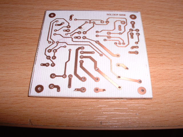
Above is a picture of the bottom, tracked side of the PCB.
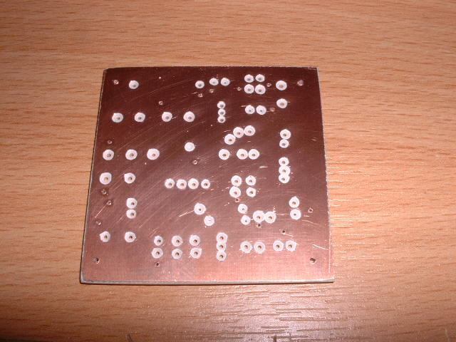
The ground plane top side is shown above. All the holes have been drilled and the countersinking done.
Assembly is quite straightforward. It's best to start with the amplifier, building it in stages (Q2, Q1 and then Q3), checking the voltages around each stage as it is assembled. Directly-coupled circuits like this can be a pig to sort out if they don't work. The other components may then be added and it should work first time. Mine did, unusually for me. 8-)
Here are details of a simple buffered VFO suitable for use with this receiver module, or with any mixer requiring a +7 dBm level oscillator input.
I'll be updating this page from time to time with details of associated circuits, such as input filters for various bands, oscillator circuits, analogue and DSP filters, RF splitters, quadrature oscillators, etc. I see it as a useful building block for experimenting with modern DC receiver techniques.
If anyone wants to build one of these, you can download the artwork for a LaserJet printer, with a parts list (including suppliers for the less easy to find parts) and detailed assembly and test instructions, including voltage checks for the amplifier construction. Here is the file: rx_module.zip
PCB designed with Pulsonix