VFO/BUFFER
It's basically a standard Hartley oscillator, followed by Roy Lewallen's buffer (page 14.20 of the 2001 Handbook). Output is +7 dBm into 50 Ohms. Don't be tempted to add a gate diode, this circuit doesn't need it, and it will degrade the phase noise performance, according to Ulrich Rohde. It should be suitable for any frequency up to 10 MHz or more (depending on how good you are at making drift-free oscillators) and may be tuned with a suitable capacitor or varicap tuning diode.
The tuning capacitor, C1, C4, L1 and T1 will need selection for the desired frequency range.
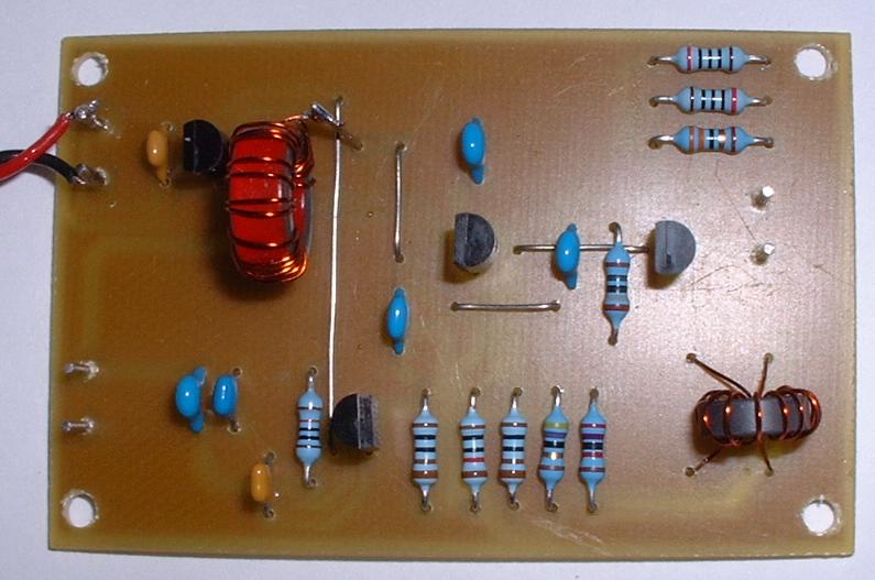
I've designed a small PCB for this circuit:
It's essential that this circuit be built into a suitable screened enclosure if using it with a DC receiver, and steps be taken to ensure that as little as possible of the oscillator signal can get into the receiver input, to minimise hum and microphonics. This won't be required if the oscillator is run at half the input frequency, and put through a balanced doubler, as is done with the Kanga US version of Campbell's binaural receiver.
R6 should be selected to give +7 dBm into a 50 ohm load - this is 1.414V peak-to-peak measured with a 'scope. I used a 130k resistor.
PCB designed with Pulsonix