Simple Class A Amplifier
Class A Power Amplifier Notes
These notes have evolved as a result of my long-time interest in both Hi-Fi
music equipment and modern electronics. I am a keen audiophile,
electronics DIYer and perfectionist - this mix constantly keeps me going.
The page serves mostly as a memo that holds my working notes. However I am
interested in reading your comments and suggestions. If you picked up some
ideas from this page and have used them successfully or not I'd like to
hear it too!
For a long time my main amps were Pioneer A-400X and Harman-Kardon
AVI-30. Both were heavily modified in preamplifier section and
high-current final stages until they stopped to show any further sonic
improvement. I am happy with both of them at the price they cost me.
Personally I prefer HK over Pioneer in a configuration with bypassed
tone/balance controls and sound processor.
I was in need of high quality headphones amplifier because of many reasons
and decided to build SDS Labs phone amp. This is extremely rewarding
project in a sense that it is fully documented, includes PCB, parts list and
building notes - so it's easy to build and then it sounds great. I have
used IRF530 and IRF9530 pairs and they work just fine given the fact that you
add 100-300 Ohm gate resistors to prevent high frequency oscillations.
This is a common problem for MOSFET designs and if you don't have a good
oscilloscope or want to be on the safe side just use gate resistors on any
MOSFET design. Ferrite beads put over gate pin could also be used instead
but I somehow prefer resistors.
SDS Labs' amp was fine but I wanted something more. At the very same
time I was repairing input stage of my oscilloscope and got very interested in
source follower schematic that is typically used in front end circuit of
scopes. Typical arrangement is JFET source follower with another JFET
providing constant current source. This gives huge input and minimal
output impedance, very low input capacitance, extremely high linearity and
bandwidth from DC to few MHz. I wanted to build something like that for
a Hi-Fi power amplifier.
Unfortunately powerful JFETs do not exist (at least I don't know of
them). The next alternative is MOSFETs but they have few drawbacks.
They need gate bias (3-4V), have much higher capacitance (due to big gate area)
and more... However this did not stop me and I have built first
prototype. It worked. And it worked darn good. It was just a
voltage follower i.e. voltage gain is very close to unity so it provided only current
amplification. Headphones were sounding great and very clean anyway.
However by design it was a class A amplifier so it was easy to overheat.
As heatsinks were warming up the quiescent current started to increase producing
more heat until I had to plug it off. It was a typical thermal
runaway. Further study has shown that MOSFETs do have this problem.
There are claims elsewhere that MOSFETs have positive gate threshold voltage termco that
prevents them from thermal destruction. It is true but only for very high
currents - in the order of tens of amperes for powerful MOSFETs. At
quiescent current that typical class A power amp uses (0.5-5A) thermal runaway
has to be taken into account.
I have spent some time thinking about that problem and found that the best
solution is to use a passive component with a negative thermal coefficient in
the gate bias circuit. When attached to the MOSFET heatsink it will provide
zero or even negative quiescent current dependence from temperature.
Negative dependence actually looks quite funny in practice - cold amplifier heats up
rather quickly then current draw gradually decreases and its temperature
stabilizes. It looks more like a thermostat! The amplifier reaches its operation condition much faster then usual class A device.
If you want such a behaviour use four or more diodes in below schematics.
It's final schematic is presented below. This is a
headphones amp and does not need high quiescent current. 100-200 mA is
fine. You may adjust it with R4.
There is similar and well researched headphone amp design by Greg
Szekeres with many others building up on it. The best from them that I
like is using LM317 to mimic constant current source. This is very easy
but requires powerful heatsinked resistors and adds more active components
(LM317 is active voltage regulator) to the otherwise pretty clean
schematic. This is why I have built mine :)
R2, C2 and D4 may be eliminated completely with a slight decrease in maximum
clipping level and M2 dissipating three times more heat then M1. Shown
schematic keeps both of them generating equal amounts of heat.
If you got interested in solid-state class A amplifiers you may find
Nelson Pass' pages interesting. However I do not share his passion to use MOSFET as
voltage gain stage without any feedback. As you see I make it simple and use it just as a voltage follower. When I need
voltage gain I just add high quality opamp gain stage.
Here is the link to my original post to Headwize discussion forum.
In my projects I have used ordinary diodes in glass package for easier heat transfer - almost any silicon
ones if their voltage drop is below 1.2V.

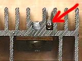
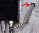
Suggested mounting is shown below. First heatsink has three diodes standing vertically with topmost pin bent back in U-shape and
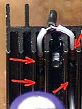
going into PCB. Second heatsink has four diodes (3 turned out to be better). Black "tail" at the top is
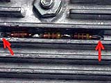
their connection point protected with heatshrink tube and bent over the heatsink to prevent movements. Third heatsink has diodes on the other side and their pins are fed through holes in the heatsink. Negative diode pin is connected straight to MOSFET's source (last image). All diode pins are protected with
Teflon tubes from the contact to a heatsink. They were all prototypes so look
accordingly.
This is my class A power amplifier designed to drive loudspeakers. Initially I wanted to use separate heavily
asymmetrical PSU biasing opamp into full class A for the whole swing of output voltage but not after I have heard it play.
The sound is gorgeous! This sound is bright and crisp. Bass is so punchy - I did not think my Tannoys Mercury M2.5 would sound so good. Actually after finishing wiring a prototype I spent two days just sitting a listening to my
favorite albums again and again...
This is the best design I have came up so far!
I use two 6x6x4cm heatsinks per channel. Power supply is unregulated (just
transformer, diode bridge and capacitors) but I cannot hear anything even when I put my ear within few
centimeters of the loudspeaker. Opamp has very good power supply rejection ratio. I've tried to keep everything as simple as possible and basically LM317
would be just one extra opamp... If you are looking for better sound, get separate regulated low power
supply just for the U1 opamp, something like +-15V at 100-200 mA.
I have also used one LM7805 to get bias for both channels - you may want to use two separate 7805 in a final
amp to get better channel separation. R2 pot is anything from 500 to 50k. I have used 22k.
To convert this to a headphone amp just use lower gain (1..3) and possibly regulated power supply. Of course idle current should be
brought down to 50-100mA.
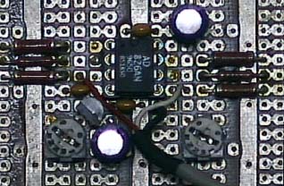
I personally prefer AD826 against OPA2604 but the difference is so small I am not even sure that it exists. The amp has so few components and is so simple that no single component can colour the sound too much. And no single electrolytics beside bypass for opamp (2x100uF), at least not in signal path!
This is how prototype board looked:
 Diodes going through the heatsink:
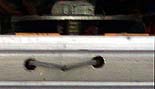
MOSFET in saturation is good constant current source by itself, look below at
the 4.5V bias curve for IRF530 MOSFET. It is almost constant drain current
of about 1A for any drain-source voltage in the range 1 to 50 volts.
Pretty impressive, isn't it?
However opamp might be used to make it somewhat better. This involves tracking the voltage drop
over current sense resistor and adjusting gate voltage to equate this drop to preset
reference voltage. I don't think this is necessary. We already have voltage following MOSFET
that tracks the input signal taking into account current source nonlinearities. If current
source would monitor the current affected by output this would create another control loop. Therefore I like
to use "blind" current source as saturated MOSFET already is and let all the subtle nonidealities be cleaned up by
voltage follower.
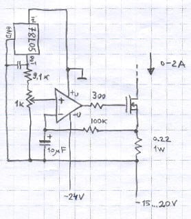
However opamp may be really useful in compensating threshold voltage temperature drift. Below schematic is such a solution.
10uF + 100k RC low pass network cuts out audio frequencies and passes only slowly changing drift caused by temperature.
If the low pass network is not used, we get above mentioned "ideal" current source (current sink
actually) for all frequency range.
Updated: I am building more serious amplifier using IRFP240 MOSFETs and planning for 3A idle current per channel. This requires massive heatsink so diode-based temperature compensation is not that easy anymore because of heatsink's size and its thermal inertia. I have built opamp-based bias circuit and using it now. I cannot yet comment is it better to use low pass filter in the current sense feedback or not.
Updated: I have built the amplifier with such opamp-based current
source and I am not sure I like its sound.
I am coming back to the original, diode biasing circuit as it gives the
best and most clean sound so far.
It is known that sound distortions decrease when overall (closed feedback) gain drops. However all the normal schematics
around use fixed gain amplifier with pot regulating its input. I want to use another approach: insert volume control
into feedback loop to vary its gain. When you decrease volume level the input signal stays the same but overall amplifier's
gain goes down to zero. This drawing illustartes the design idea:
Total amp gain is 0...10.
Of course there is a drawback: amplifier's output becomes inverted and speaker terminals should be reversed to keep
correct output phase. I don't see any problem here. Do I miss anything else?
Even more, input impedance increases from 10K at full power to 110K at very low sound levels. Noice and static also should
go down to zero as gain drops.
There was a discussion about using mouse-type optocoupler system to step up/down a reversable counter that will control DAC used to vary gain. This is a simplest schematic to decode optocoupler's outputs into separate up/down pulses to drive the counter. It generates one pulse per each hole passing the sensors.
HomePage
Leo Bodnar, (c)2001