Improving OpAmp's Performance
OPA2604 (Burr-Brown)
Leo Bodnar, 2001
When designing a new circuit or choosing between existing ones you have to settle on the level of components that you consider adequate for set goals. It is very easy to get into emotional discussion of how good valves in general as compared to opamps in general. But let's say we or someone else have decided to use opamps. Even which opamp to use (this may be heavily influenced by such factors as availability, price, etc..) Let it be OPA2604 from Burr-Brown.
Let's see if we can squeeze a little bit more from already good OPA2604. Careful study of its datasheet reveals a lot of fine details.
1. Total Harmonic Distortion (THD)
We want as minimum THD as possible. Announced 0.0003% distortion + noise is achieved for output signals with peak-to-peak voltage between 3 to 10 volts with minimum at about 6V. Possibly noise floor is relatively independent of input signal level therefore THD is at minimum for signals with output amplitude of 3V.
So THD is increasing as output gets smaller. This is not good and this is probably caused by crossover distortion in output stage. Distortion also increases as output becomes too large. That increase is possibly caused by nonlinearity of input or middle gain stages as their output get closer to supply voltage. However 20V output swing will have the same distortion as 1V. See datasheet log graph below (I've also created linear version):
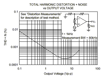
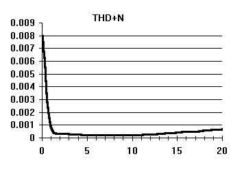
What it boils down to for me is idea to shift operation point such that opamp's output would not be at zero anymore when input signal is zero. Idle voltage of 2-5 volts is fine. Original graph is for +-15V supply voltage, 25C temperature, unity gain and 1K load. I don't know how it would look like at +-24V supply voltage but I do not expect strong change here. It would be interesting to know how the lowest distortion point shifts as we increase supply voltage. Does it stay there or follows supply voltage? I don't know but definitely it will not end up at zero volts output where everybody asks opamps be at small signal (typical buffer, inverter, filter, etc.).
Final suggestion: shift operation point away from problematic zero output point.
2. Gain level
THD also depends on overall gain. This dependence is almost linear - increasing gain from 1 to 10 causes THD to grow 10 times. Then we have to use gain sparringly - just enough what we need and not more. Setting more gain then needed and then keeping input low is not good practice. Adjustable gain settings would be reasonable for matching with input source. I am not sure if pot is OK given its linearity and stability problems, but few discrete resistors possibly selected with good quality relays/swiches/jumpers seem appropriate.
Final suggestion: use only needed amount of gain, not more.
3. Power supply ripple rejection
So world seems to like symmetry? Not exactly. Look closer at power supply rejection curves. While they are the same at low frequencies as we move higher, the negative supply ripple rejection becomes 34dB worse than positive one! Opamp is 50 times more susceptible to high frequency noise from negative power rail than from positive one. At 40kHz positive supply rejection is 8000 times and negative is only 300. Traditionally (from PC and digital times?) negative voltage PSU are considered same or even less important then main positive voltage sometimes negative voltage is even generated from positive. But high quality opamps sometimes needs just the opposite.
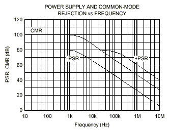
What is the reason? I just may wildly guess that because of inferior specifications of holes-conducting devices (pnp BJTs or p-channel JFETs) as opposed to electron-conducting (npn/n-channel) the negative side is not as good as positive (that uses pnp/n-channel).
Final suggestion: get much better high-frequency decoupling for negative rail.
4. Power supply voltage
Let's look how supply voltage affects different parameters.
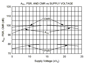
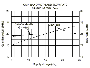
Designers definitely compensated the opamp for +-15V operation. There all sorts of rejection get their maximum efficiency. However slew rate steadily increases with power supply voltage.
Final suggestion: use +-15V PSU. When driving output transistors directly, increase power supply voltage to +-24V.
5. Thermal behaviour
Don't forget power dissipation and thermal behaviour.
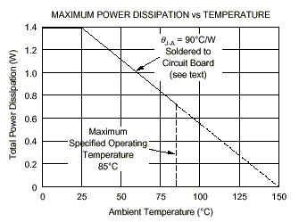
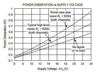
With temperature increase to 85C maximum output current drops from 40mA to 30mA. Any high-voltage or high-current design involving this opamp needs separate thermal calculations. However notice that 90C/W junction-ambient thermal resistance includes PCB it is soldered to! One less reason to use sockets.
Final suggestion: take power dissipation into account. Do not use sockets when extra heat dissipation needed.
In any way have fun and use all information you can get hold of to improve your designs.
HomePage
Leo Bodnar, 2001


