 |
| MINI ROVER |
| LEGO MASTERS |
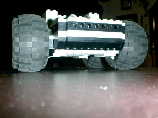
| The mini rover consists of a dual transmission setup running off of two motors. It follows the skid-steer principle of many robots (I think the LEGO ROBOTICS CONSTRUCTOPEDIA even has a few variations of this type). This type of drivetrain is also found in many real-life devices such as military tanks, bulldozers and probably most commonly the bobcat. However, this design has been specifically designed to provide excellent ground clearance, manuverability, power, and relative speed in one model. The frame can be easily adapted to climb smooth 45 degree inclines thanks to the four-wheel-drive system. The gear system has been kept simple to minimize friction. I have designed a number of similar sized chassis using worm gear drives and found that this only reduces both power and speed, which is not a desirable trade-off although providing a lower overall profile with the same ground clearance. The main aspect of building this model is that it offers a lot of just plain fun after it's built. Use your imagination. With enough patience and one extra motor, I have been able to build a dozer, forklift, bobcat, explorer-bot, and the neatest of all I think the BOMBOT, which actually uses a robotic gripper set to pick up objects. I've found that depending on your driving surface, different wheels and tires will provide different handling characteristics. Below you'll find the ML-CAD file for the Mini Rover 1.0. This version uses worm gear drives which are slower. I'll post the direct drive soon which is much better. |
 |
| SOME THINGS NOT MENTIONED IN THE INSTRUCTIONS |
| I did not insert step numbers in the pictures. I did not specify the axle sizes in the instructions; the axles sizes are as follows, from the motor to the wheels in that order: Primary shaft: # 3 studed Secondary shaft: # 5 Final drive shaft: # 4 Ground axles: # 6 or # 8, depending on wheels used. The collars used on step 24 may need to be replaced with full collars depending on wheel used. |