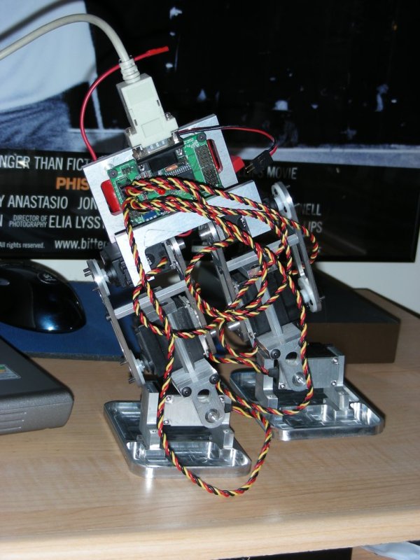
Morbo is a biped robot I designed and built to experiment with. It is intended to be a continually developing platform to test various methods of locomotion and processing. Although there are currently several biped kits on the hobby market, I've decided to " roll my own " so to speak. I love machining and building, and I have a few things I haven't seen before that I'd like to try.
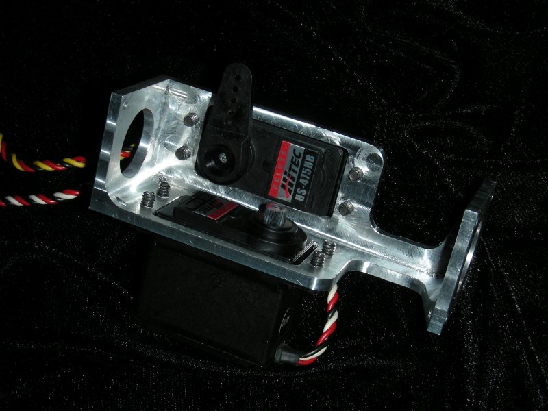
The above picture shows Morbo in almost the current configuration. Missing in that picture is the wireless link. The current incarnation consists of:
6 Hitec 475HB Servos
PicoPic
Serial Servo controller
Sparkfun Electronics Blue SMiRF
Bluetooth radio
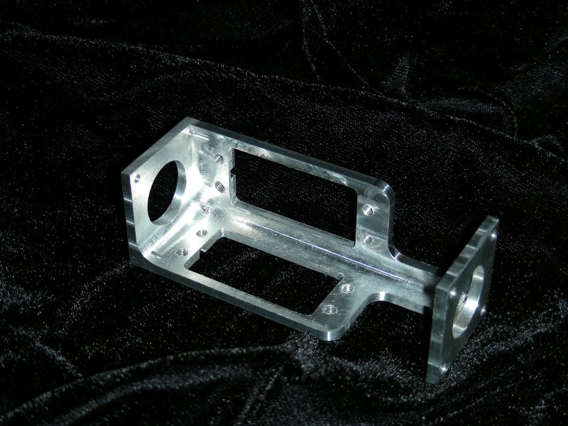
Custom build aluminum chassis
1500Mah 7.4v LiPo Battery
Medusa Electronics 3.5A BEC
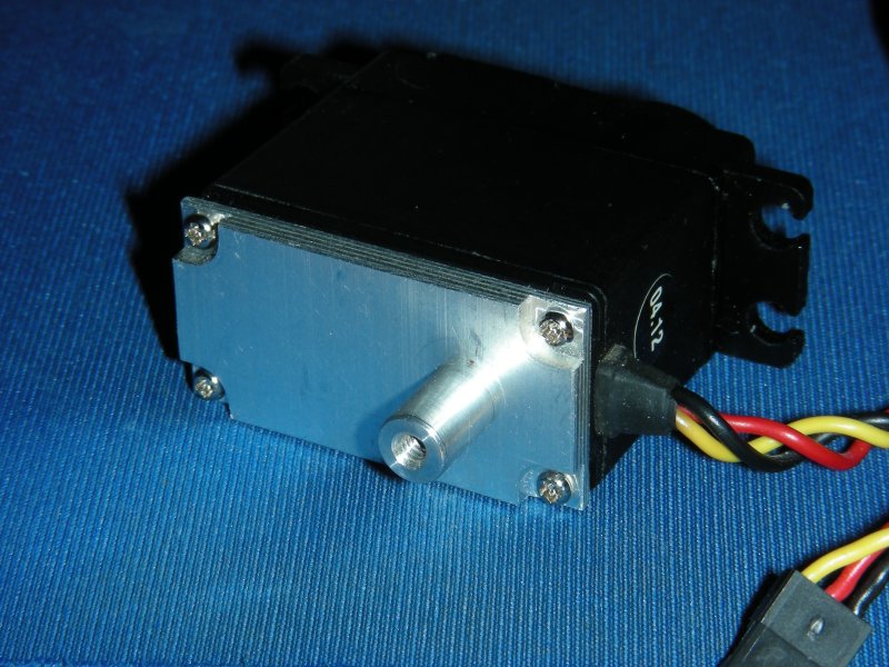 |
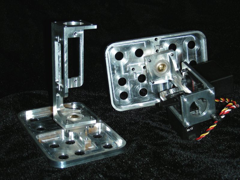
Way back when I started this project, the first thing I did was to make these, pivot brackets for the rear of the servos. Commercial units that do the same thing frequently attach to the servo case with double sided tape or glue. I don't like either of those options. These use the existing screws that hold the servo case together. The post sticking out is simply a threaded aluminum spacer. It provides a .25 " post directly in line with the servo's output shaft. With this I can make the entire servo pivot on bearings, double supporting any loads. Attempting to hang even one limb off the single bearing in the servo case is a sure way to kill servos. Unlike many servos used in bipeds these days, these are analog servos, and are quite cheap. Many people use digital servos for increased holding torque speed and all sorts of other stats. While I will most likely move some or all of the servos in this project to Digital servos in the near future, I feel it's important to show what can be accomplished with budget level servos. |
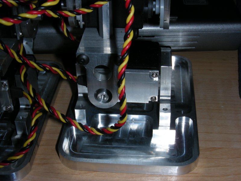 |
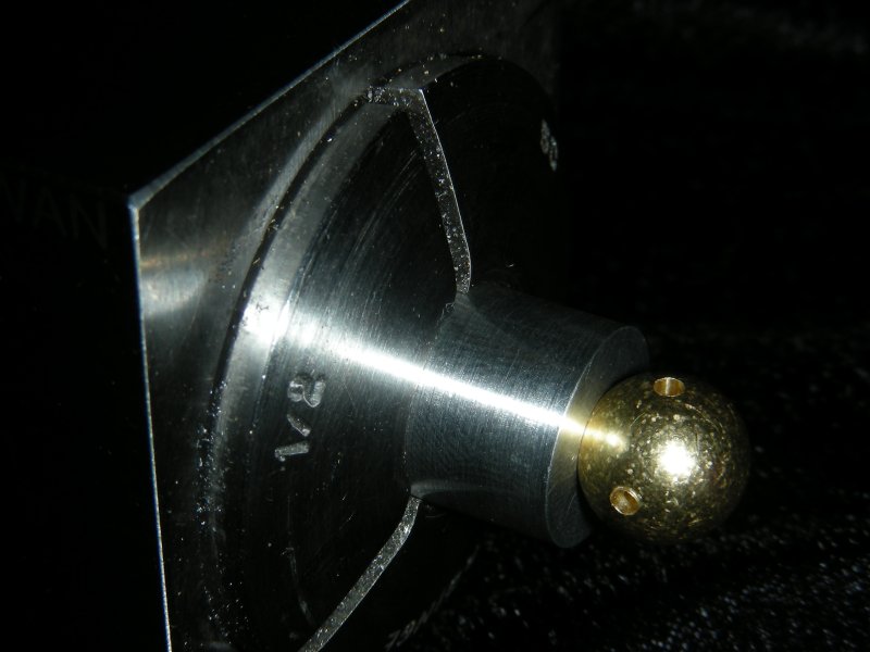
Here's a closeup shot of one of the feet. The rounded front bracket holds a ball bearing that rides on the servo backing plate. The footplate itself is in it's third itteration. I wanted something smaller, and with a smaller heel than toe area, but it proved very difficult to make balance and walk. |
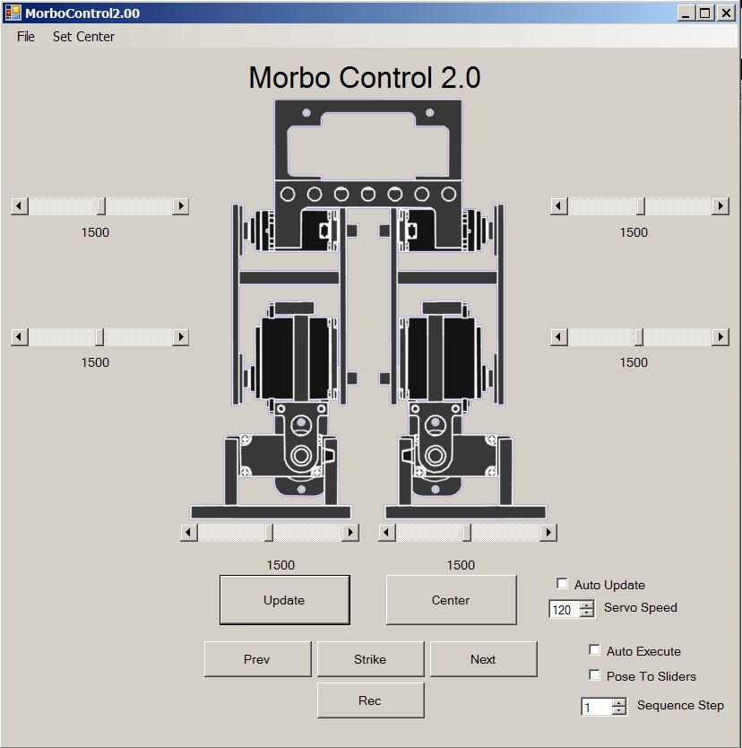 |
There are several different ways to control a project like this. While I have several flavors of Basic Stamp on hand, as well as AVR dev tools, I chose to begin this project using my PC to control things. When I first began this project a couple years ago, I had looked into some PC dev tools, but didn't feel like spending too much on them. I took another look this year only to find that Microsoft had released free Express versions of their Visual Studio tools. I chose Visual Basic for this project, mainly to speed up coding to make something that just works. The result is the program you see here. For the moment, the program allows me to move the sliders to position each servo, as well as define center points for each one. It also provides 20 " Pose " positions which can be stepped through in order to create a walking sequence. Both the center positions and pose positions can be saved, the results are in a plain text file, which will allow me easy access to reading what moves go into what sequence. The PicoPic board which handles the timing pulses for the servos expects serial data. Communications are handled with a Sparkfun Electronics BlueSMiRF Bluetooth radio. With a cheap USB Bluetooth adapter and software, it created a virtual " COM " port that behaves exactly like a phyiscal port. The whole system is very transparent and easy to use. |
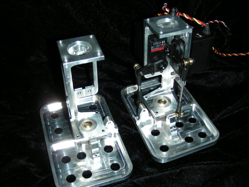
The link at the left has some very dark low res video of Morbo's first step. Not enough light, and not the right settings on the camera. I promise I'll do a better job next time. So where to from here? Although I am excited that I have a walking platform, there is much to be desired about the current chassis. It's fairly heavy for one thing, some habits from combat robots are hard to break. Although the rear servo brackets are one way to completely support joints, they make a lot of trouble aligning things, and also add to excess weight. The weight is also spread throughout the leg, making it more difficult to position the leg that's off the ground. To address these issues I have redesigned the chassis with the following in mind : |
 |
Morbo version 2 contstruction begins with these parts which will form the thigh. They were machined out of blocks of 6061 Aluminum. I have quite a bit of this stuff lying around. These parts were designed such that later on, when I expand the robot to more degrees of freedom, this can function as a lower leg. |
 |
The thigh parts serve as mounts for two servos. These servos will tilt the foot in two axis of motion. The leg was designed to move the servos as far away from the foot as reasonably possible, making it easier for the hip servo to swing the leg around. Just about every other design I have seen places at least one servo on the foot itself. That places a lot of load far out on the leg. When leaning over onto the foot which is on the ground, you have gravity on your side, as the weight of the robot holds it down. The leg that you are moving through the air has no support at all, and the servos bear all of the load, the hip servo bearing the most. This is my attempt at lowering the load that servo sees. Because the servos mount from behind the parts, as long as the servos have the same mounting hole pattern, they will fit. No need for a back plate. This will make the transition to stronger servos later much easier. |
 |
A couple of more parts done. These were supposed to be made of UHMW. The problem with using UHMW is that it does not like to cut cleanly. Instead of forming nice defined edges, it will curl over. This part depends on precisely location edges so having a burr is not acceptable. Removing the burr generated in the UHMW makes the situation worse in the opposite direction, as the tools tend to dig in. In order to keep the part precise I used Lexan instead, as I happened to have some lying around. |
 |
This is what those parts do, two of them sandwich a brass ball, to make a ball joint. Off the shelf parts didn't offer the range of motion that I wanted, so I designed these to fit. I still need to drill and tap a hole in the brass balls. The ball joints will allow the foot to pivot in two directions about the same point. Technically this joint would allow motion about three axis, but I am only using two. This will hopefully mimic the human foot more than the typical arrangement of a servo flat against the foot and one above it. |
 |
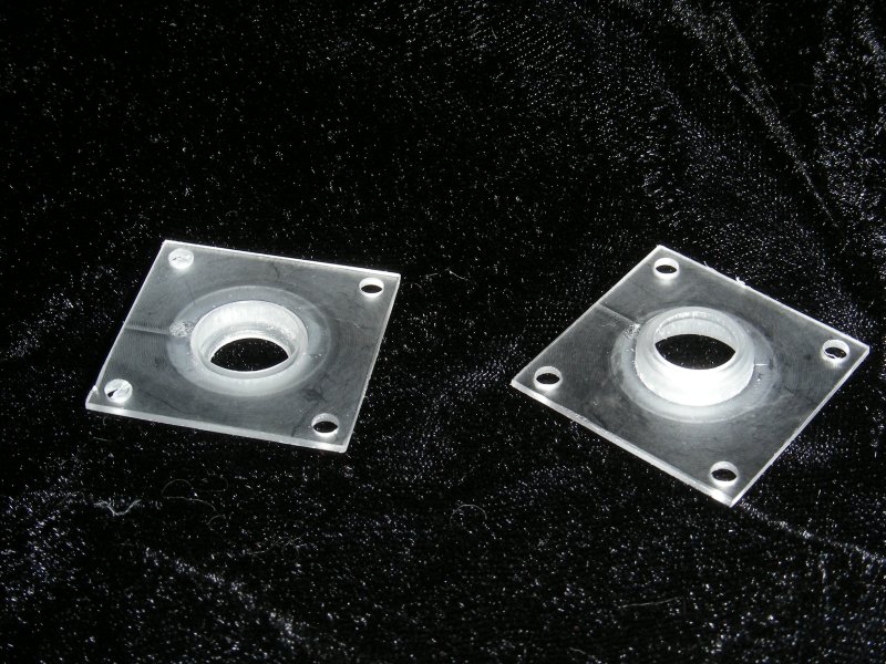
Since the new servo mount needs a different system for attachment to the feet, I made up a new set. I also took the opportunity to put in a couple holes to reduce some weight. There is a spacer missing between the ball and the foot, I don't have the correct length of screws or the spacers, but they are on their way. The foot plate will be actuated by control rods from the servo horn to brackets which mount on the foot plate. The brackets will allow everything to line up correctly. I will have a little bit of room to play with this system, and as I'm not trying to get 180 degrees out of the servos, I should be able to mount the pushrod a little further out on the servo arm, gaining leverage but sacrificing range of motion. I should basically be able to gain leverage with no decrease in range of motion. |
 |
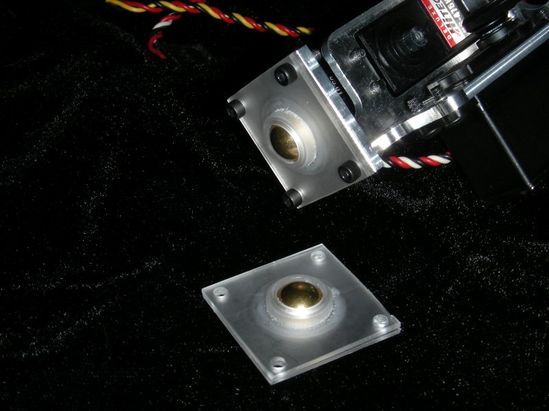
Here I have made the attachment brackets that join the servos to the feet, and installed a couple of servo horns and pushrods. Still missing is a critical anti-rotation bracket. I wasn't 100% sure as to how to implement this until today, now it's just a matter of putting it into metal and plastic. Without this bracket the joint can pivot on it's third axis, causing inconsistent twisting motion. The other good news is that the comparable parts in the older version of Morbo weigh 9.6oz, and these are 7.4oz, a 23% savings over the original. The missing bracket will add a little, but not an appreciable ammount. More importantly, the weight has been shifted closer to the top of the leg. |
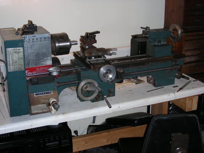 |
Although the last pics show a decent ammount of progress, I'm not totally happy about the way the ball joint is going. When I installed the anti-rotation bracket, range of motion was compromised somewhat. The bottom line is that things can be a lot better with a little redesigning. I've also come to the conclusion that having the HAAS CNC machine available to me at work is a somewhat bad influence. It's easy to make whatever I want, but what I want inevitably turns out to be what's easy to fabricate on the work equipment without disturbing things too much. It's time I got my home shop back in order. Enter my new friend here. An Enco 9x20 lathe, which I bought from a friend at work (Thanks Jim!). It's been well treated, and although it suffers from a couple of minor shortcomings common to Asian import machines, with a little work it will be quite capable. I've already put in a couple of mods that have improved finish greatly and cleaned things up pretty well. I changed the original compound rest hold down to a custom made 4 bolt version instead of the wimpy 2 bolt that comes stock. I still need to make a camlock system for the tailstock and a couple other things as time allows. I've also got some plans for improving my Sherline mill as well. More on that as I get to it. |
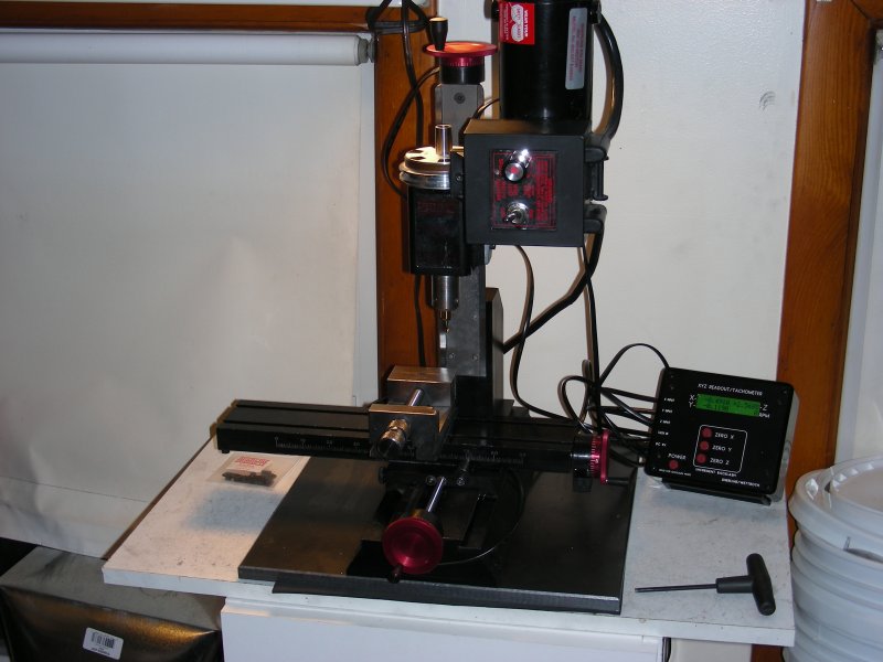 |
Here is the upgrade to the Sherline mill. It's served me well when I didn't have access to another larger mill, now I plan to do more work at home with it. They are tremendously capable for their size, and have many upgrades available including the one I just installed, the DRO or Digital Read Out kit. On larger size mills a digital readout uses scales to read the absolute position of the table. On this mill optical encoders read the turns of the lead screw with a programmed compensation for leadscrew backlash. There's a lot of talk online about the limitations of such a system, but like it or not backlash is a reality when dealing with leadscrew systems like this one, no matter what. The only way out would be to install ballscrews, but that's a whole lot of cost for a machine that can be just as accurate if you take your time and know what you are doing, working around the backlash. The digital readout on the other hand makes life a whole lot easier if not for the fact that it frees me from having to remember turns of the handwheel. I've gotten really used to this system on the Bridgeport at work, it makes things a whole lot easier. I also mounted the mill itself to a heavy steel base plate. The extra mass should help with stability, as well as making a handy place to attach magnetic bases for holding indicators. I took the opportunity to give the mill a thorough cleaning as well. Now that I have a capable mill and lathe set up at home, prepare to be bombarded with pictures of machining in progress. |
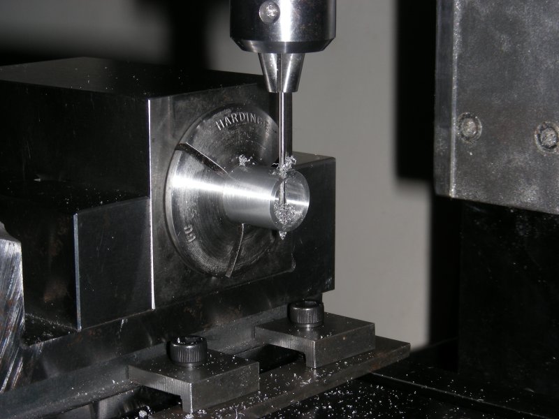 |
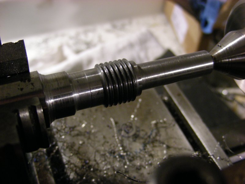
With the machines squared away, I can begin work on a couple of parts. First I turned a piece of 7075 Aluminum to diameter on the lathe, and bored the center to a couple thou over .375" . I then parted off and grabbed the result in a collet held in a block chuck. It's the square block you can see. It allows you to hold something in a collet centered in the square. This lets you do one opperation, spin the block, and do the same opperation again to another side, and they will be equal. There is a hexagonal block as well, it would be used to machine the flats on a hex head bolt for example. The opperation shown here is not drilling, but rather reaming the hole through the tube. Reamers provide a very precise hole diameter in this case .0630" just a half a thou over .0625" . This will allow a 1/16th of an inch dowel pin to pivot freely in the hole. |
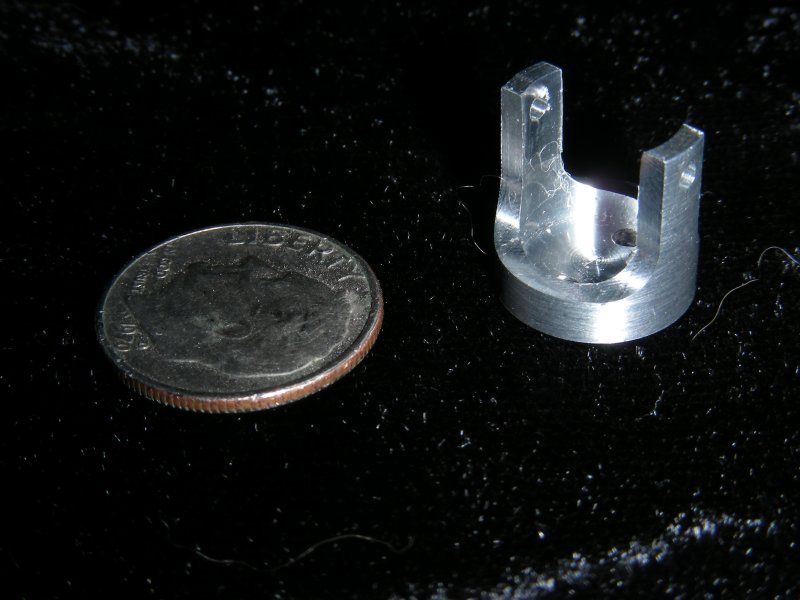 |
Using the block chuck, the two sides of the tube were shaved down equally, and the bottom trimmed off. The resultant part is shown next to a dime for scale. This part will be a yoke for a new " U" style joint for the ankle. This style of joint will allow free pivoting in two axis, while restricting third axis motion without any sort of external anti-rotation brackets. 7075 Aluminum was chosen for both it's superior strength over the more common 6061, and it's ease of machining and superior finish. |
 |
Another day, another tiny part. New here is the second yoke for the " U " shown here with the brass ball placed in the center. The ball needs a couple of opperations before it's done, to hold the pivot pins that will make the joint pivot. |
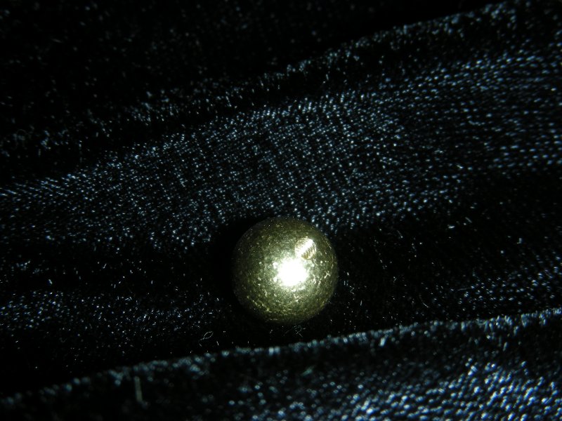 |
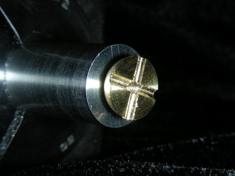
Today I made the spiders that go in the middle of the " U " joints. I started out with brass balls from my favorite supplier of all time www.mcmaster.com. A 2-56 hole was drilled and tapped in the ball to begin the process. |
 |
Using the hole tapped in the previous step, the ball is grabbed with this jig, simply a cylinder with a hole size of a known diameter in the center. This grabs and holds the ball in a repeatable centered position. This jig is grabbed in the block chuck, and the 4 sides of the block chuck are used to spot, drill and ream 4 holes in the ball. These are sized just a hair over 1/16th of an inch. |
 |
While I certainly could have just drilled 4 holes and pressed the pivot pins in, I really dislike methods like this that I can't disassemble later to repair or replace parts. So instead I made it so the center spider was in two parts to clamp the pivot pins between them. Using the same jig, I chucked it in the lathe, and removed just over half of the ball. Why over half? To allow some room to clamp down on the pins. |
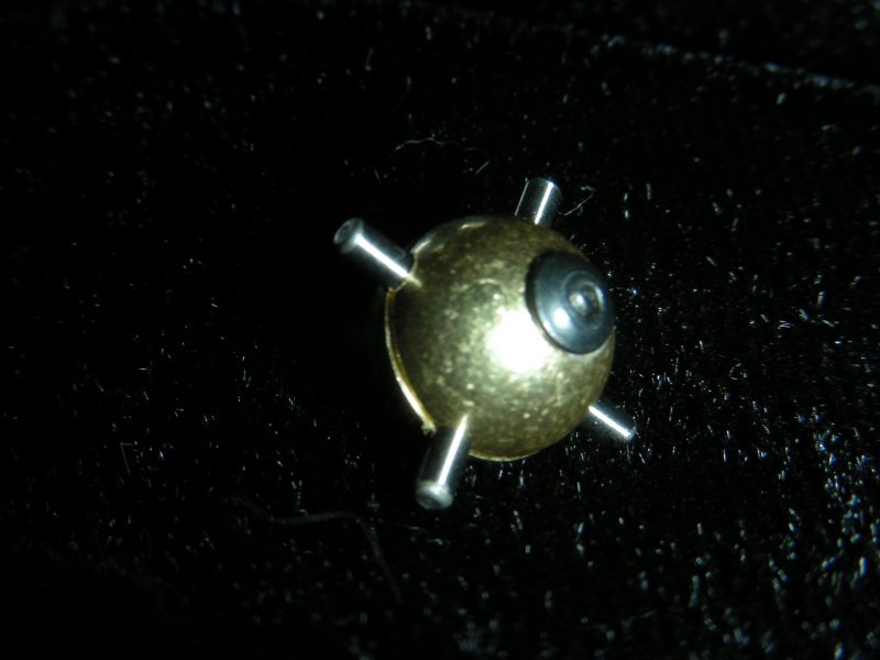 |
Repeat the above steps a second time, and finish by boring one of the tapped holes out to clear the shank of a 2-56 screw. Leave the threads in the other half so that the screw can pass through one half, and into the threads in the other to clamp the result together. Here is the spider assembled, with 4 1/16th x 1/4 inch dowel pins (the smallest that McMaster had). |
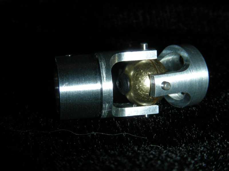 |
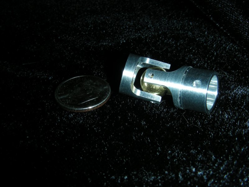
Here is the complete " U " joint. It works very nicely, and is the exact part I wanted. While there were similar products available, they were not the size, weight, or material I wanted. They were also rather expensive and non-disasembleable for repair. |
 |
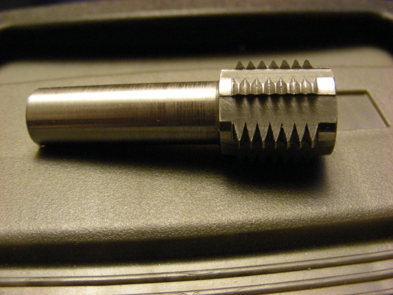
Another part of the project I'm really looking forward to is making gears. There are several methods of generating the correct shape for a gear tooth. The most readily available method involves buying a specically made cutter. Problem is that these cutters are not cheap, and require a set of 8 cutters to cut the range of gears from 12 teeth to rack. They also require their own arbor, adding more cost. While I'm all for buying tools, there seemed like there should be another way. Commercially produced gears are often formed with a hob. A hob is a spiral cutter for generating gear teeth used in a gear cutting machine. The cutter is synchonized to turn in a particular ratio with the gear blank and the blank revolves as the hob shapes the teeth. As one might imagine such a machine is rather specialized, not cheap and does have a couple of limitations besides. The method I've chosen here is a variation on a process called the " Sunderland " process. In that process a shaped cutter is moved accross the face of the gear shaping the teeth. The cutter is shaped like a rack gear, and while cutting one tooth to full depth, the other faces of the cutter shave small bits from the teeth next to it, refining the involute gear tooth profile. Instead of a shaper I've decided to make a cutter for the mill instead. The cutter begins as a length of S7 rod. I turned the outer diameter and shank diameter. Because I'm lazy I decided to make these 30 degree pressure angle gears. This let me use a standard carbide 60 degree cutting tool to make the tooth shape. Basically you can imagine taking the profile of the negative of the rack (if run against a flat surface this cutter would make rack teeth) being rotated about an axis, this is what you would have. |
 |
The cutter is finished by taking the mill and cutting accross the blank, making teeth. These are not profile relived teeth, but they will do in this situation. The cut was made slightly off center so as to give the teeth some rake. A little deburring, and it's off to the kiln to be hardened. This time I'm trying a little something different, instead of just throwing the cutter in there, I found some stainless steel envelopes for heat treating. Hopefully they will keep interation with the air to a minimum and minimize the carbon scale that builds up on the surface during hardening. |
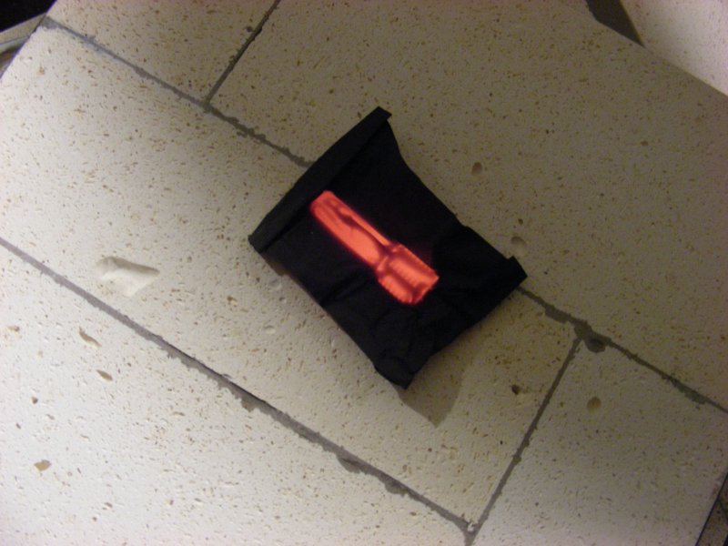 |
Kirstin is quick with the camera and managed to snap this shot of the cutter coming out from the kiln. Heat to ~1725 deg F and this is the result, litterally glowing through the foil wrap. After it cools to room temp in air, I'll reheat to about 300 degrees to temper. S7 is an air hardening steel, so there is no need for quenching in oil or water. |
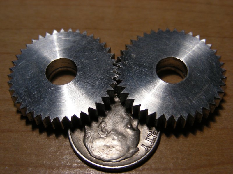 |
The hob came out pretty well. The stainless envelope worked great, there was no scale on the part to have to clean off. To see if all that was worth it, I cut these test gears. I had a chunk of 1 " 6061 sitting around, some quick calcs showed an easy 40t gear could be cut from it with a .875 " blank diameter. For those interested the equasion for blank diameter is : Blank diameter = (Gear teeth + 2)/Diametrical Pitch -or- Blank diameter = (40 +2)/48 To figure out the tooth spacing simply divide 360 degrees by 40t for a relatively simple 9 degrees. The blank was held in a chuck on the rotary table, and each tooth cut. The process seems to have worked pretty well, leaving a good approximation of an involute tooth. It's certainly good enough to cut the rest of the gears for the project. Since these were quick test, I didn't take the time to take pictures of the various steps. Stay tuned for some more detailed pictures of the other gears. |
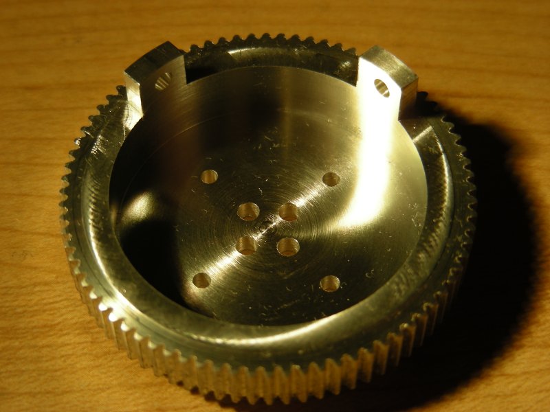 |
Since I'm redoing things, I figured that I may as well add a couple degrees of freedom to the legs, namely the three in the hip. Tilt from side to side and forward and back will be handled with one of the universal joints. Rotating the entire assembly will be handled with a set of gears. This is the gear that the entire leg is mounted to at the top of the hip. Using the hob and making a couple of minor adjustments to the depth of cut from the test gears, I cut one of these. 80 tooth, with a .25 face width. The two " ears " are to mount the pushrods to the servos. When the " U " joint is placed in the bottom of the cup, the pivot axis is lined up with the holes for mounting the pushrod ball joints. Since I was more worried about getting the part made correctly I didn't stop to take pictures along the way. For the second one I plan to. |