Ford 2.3 Turbo
The engine specifications are detailed below This includes a totally stock fuel injection system with small VAM. Modifications include:
16 psi. boost pressure
14 deg BTDC ignition setting
T04B(h-trim)/T3 turbo
Slightly modified Later style (revised) exhaust manifold
Ported big valve cylinder head
.500" lift roller cam
Underdrive crankshaft pulley
Complete 3" exhaust system turbo to tailpipe
Spearco intercooler system designed for SVO mustang
Wiseco forged 7.8:1 CR, full-floating pistons
Childs&Albert trackmaster rods
Total Seal "gapless" rings
Future modifications to come in the following months:
Install larger Vane Air Meter
Modify upper intake manifold
Build water injection system
Now for a more detailed description of the parts:
Pistons
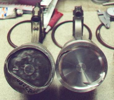
Stock Forged Ford vs. Wiseco Forged
On the left is the stock Ford pistons that are good quality but now obsolete, thanks Ford! On the right is the Wiseco 2618 Aluminum alloy forgings. Both pistons are set so the front of the block is to the left. As you can see, the Wiseco piston has a deeper dish that will drop the compression ratio at least 0.2:1. The bigger problem with the piston is the fact that the dish does not match the stock combustion chamber profile as the stock piece and as a result, you loose some squish area. This is bad because it can lead to early detonation. The Wiseco has big valve reliefs in them that allow the use of larger than stock valves and allow cams up to at least .550" (maybe more) lift without piston to valve contact even if you loose the timing belt. Both pistons have the top ring set .250" down from the top to protect the first ring from the hot gasses and work with 5.2"rods. However, the Wiseco piston is set up for full floating pins. I purchased the set of 4 Wiseco pistons, pins and locks for $348 in late 1999 from Racer Walsh. They are also available individually if you melt one down.
Rods
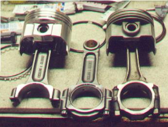
Childs&Albert Trackmaster vs. Stock Ford
On the left and center are the C&A "Trackmaster" rods that fit the stock pins/crank. On the right is the stock rod. The C&A's are made of AISI 4340 steel (Chrome-Nickel-Moly alloy .4% Carbon) and have 7/16" capscrew fasteners. I have personally weighed them at 670g with a variance of no more than +- .5g, so you could consider them balanced as delivered. When I installed them in my crank that had 100Kmi and a polish job, they had about .006" side clearance on them. I narrowed them down by to provide about .008" side clearance by putting 1000 grade sandpaper on a known flat surface and sanded the side face. As you can see from the photograph above, the beam is much wider at the top and the caps are beefier too. Another interesting note is that these rods will eliminate the oiling hole which is barely visible in the photo above on the right side of the base of the beam. For a better view, look at the previous picture of the pistons or photo below and you will see the oiling hole and boss on the stock rods. Eliminating this feature does two things. The good thing is that it will eliminate the stress concentration in this area that the hole causes which can cause fatigue failure. However, this also will stop some oiling of the on the passenger side skirt which sees the most side load under power. The stock pistons that I pulled out after about 100K miles had very little wear on the oiling side of the skirt, no doubt due to this feature. The C&A rods also have a much better surface finish on the beam which will help the fatigue life. They cost about $82 ea. directly from C&A and are available in pressed or bushed small ends.
Rings
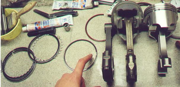
Total Seal "Gapless" Rings
In search of a better sealing piston ring, I purchased the Total Seal "Gapless" ring set. C&A also makes a "Zero Gap" ring set, however I did not know if they were available at the time for my particular application (which is metric) with the Wiseco pistons. The "Gapless" ring is actually two rings that fit in the second ringland with one nested on top of the other's outer recess. Each ring has its own end gap (that you file to fit) and the idea of it being gapless is that you place the gap of each ring 180deg. opposite the other in the ringland. As you can in the picture above, my finger is pointing to the area where one ring overlaps the other. Supposedly, it is possible for the gaps to align if they rotate over time which would nullify its advantage. In my case, this would even make things worse since I filed the top ring's end gap on the loose side to allow for thermal strain (expansion) during prolonged full throttle conditions (Banzai!). This was to reduce the likelihood of the endgaps meeting under those conditions. That is the nice thing about the "Z-gap" rings which use a offset groove machined into the ends of the ring which lay on top of each other to try and seal the end. I installed the rings "dry" which means to use a sparingly applied lightweight (low viscosity) oil to the cylinder walls and that's it! This is supposed to reduce the break-in time. I paid $108 for the ring set from Racer Walsh since the rings are metric to go with the metric sized ringlands in the Wiseco pistons.
Cylinder Block
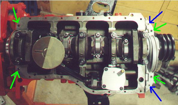
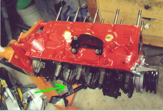
1986 and older vs. 1986.5 and newer block oilpan holes
There is a common problem that many people run into with oilpan gaskets for these motors. Ford changed the bolt pattern towards the end of 1986. Above is the older bolt pattern. The super-duper rubber gasket that you can buy from Ford is designed for the later block. I purchased one and modified it to fit. However, I recommend that owners of the older block stay with the stock rubber/cork gasket if you don't update the front cover and rear main cap which does not have the groove that you can see above. Now for the mods. First of all, the holes that the blue arrows are pointing to on the front cover don't exist on the later block. This can easily be changed by drilling the two necessary holes in the rubber gasket. The holes that the green arrows are pointing to are smaller on the newer blocks. This is a PITA since you must now either remove the steel compression limiters that the rubber gasket has molded in (which I did) or try and drill the limiters out to the right size. Good luck with the later approach since holding the gasket down is almost impossible and if you don't then the gasket becomes a big whip just itchin' to hit you in the face. To make the ends seal you will have to use a huge amount of sillycone or machine some sort of insert to fit the groove and take up the gap. I used sillycone and it leaks a little on the front and back.
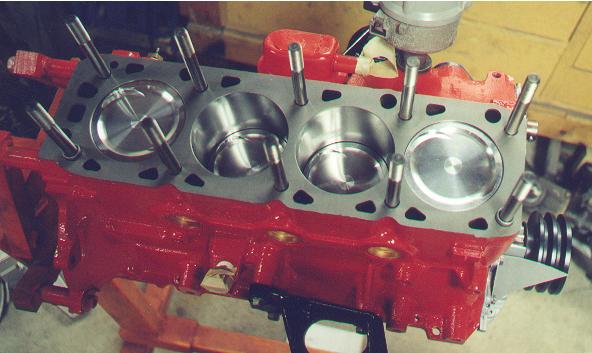
Assembled Shortblock with Head Studs and dowel pins
Main/Head Studs
Modified Oilpump Pickup Bracket
Ok, here's the deal. If you are gonna run main studs ('cause you should if you're making over about 350lb*ft of torque) then you are going to have to modify the oilpan and the oilpump pickup bracket. At least the studs I bought from Esslinger needed these mods. First let's start with the oilpan. When I tried to put my pan on, the rear main stud ends would hit the rear of the pan. The solution was to take a ballpeen hammer and add the clearance to the pan. Fixing the pickup bracket is much more of a PITA. The problem is that the stock studded-end main bolt that the bracket is secured to is now replaced with a stud. The stud is not long enough to use spacers so you will have to elongate the hole on the bracket and rebend it to fit. This will require trial and error fitting and I accomplished it by hammering the bracket flat and then rebending it by hammering it in a vise. By the way, if you are using the stock oil-water oil cooler then you should use the stock "turbo" oilpump since it only has an increase in pressure of 15psi over stock to cover the pressure drop the stock oil cooler creates. If you use the high-pressure and/or volume oil pump then it is only a matter of time before you break the intermediate shaft the drives the distributor and in turn drives the oilpump. In fact, if you run a more efficiently flowing cooler then you could get by with the stock pump. This is important advice.
Esslinger Crank Pulley and Pointer
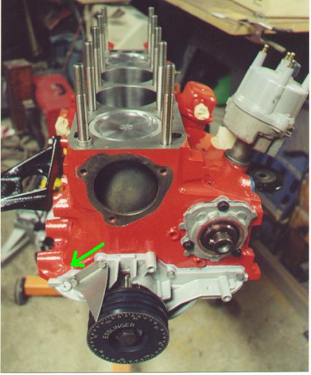
The Esslinger 2-groove Crank Pulley and Pointer
This is my experience and first I will tell the good stuff about the pulley. It is a very nice piece of Anodized Al and comes with very precisely laser etched marks and numbers. I purchased it mainly because I wanted to degree my cam and this was the cheapest way to do it. Actually, with a sharp-ended pointer you can get very accurate and precise results from this pulley compared with the typical 12" degree wheel. In addition, if you are turning a lot of rpm then this will slow everything pulley driven way down. This can also be a problem on a street car. Now for the bad part. My '86 tbird has the old crappy ford alternator and at idle the charging system is discharging. I don't get maximum output until the mid 2k rpm area and the power steering pump is not turning fast enough for maneuvering at engine speeds below 1500rpm so the steering will suddenly get a little heavier and can be a bit surprising if you are not prepared for it. My biggest gripe is with Esslinger's pointer that is supposed to match the pulley. As supplied to me and bolted onto the front cover as specified and show above, the pointer is 5deg. advanced. So when I found top dead center (and yes, I know several ways to find tdc and can do it well) the pointer was pointing to 5btdc. I talked to someone with Esslinger Eng.,and after trying to describe the problem and confirming that I had the right parts (or at least part#s), I asked him what he was going to do about it. Well, he basically said that he didn't know what to do and so I had to fix the problem myself. The solution was this. I elongated the holes to the right (as looking from the front of the motor) and chopped some material off of the left side of the pointer near the bolt so it will slide as far as it will go to the left (direction of green arrow). After taking it as far as I could make it go, it is now 1deg. advanced and I accommodate it in my readings. The pulley only cost about $45 and the stainless steel pointer was $5.
Cylinder Head
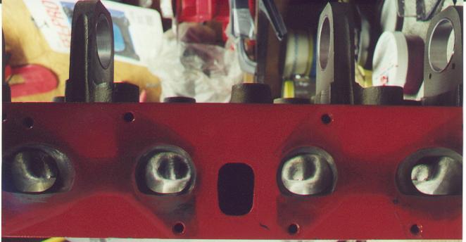
Intake Ports on D-port Cast Iron Turbo Head
Now for the stuff that actually makes power. The philosophy behind the port modifications were to make them flow more while not killing gas velocity which would make an already weak low-rpm range even worse. I have no idea if what I did made things worse or better for the low-rpm because I changed the turbo at the same time and it's too damn big and won't make more than about 8psi until over 3200rpm. At any rate, the head has been fitted with 1.89" intake valves and 1.59" exhaust valves. The port work involved raising the roof some and removing some of the valvestem guide boss while removing a very small part of the short-side radius and only cleaning up the port floor. In retrospect and after talking with someone, I believe that that the guide boss could be made even smaller and maybe open up the top even a little more. On the exhaust, the port turns into a circular hole after the bowl and in that hole I only increased the radius no more than about .05". The bowl of the exhaust is what received the most work on that side.
Other Pieces
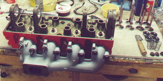
So-called "E6" or Later Big Exhaust Manifold with Assorted Valvetrain
The exhaust manifold above is a brand new part from Ford and cost me $138. If you upgrade to a T4 compressor then the wastegate bracket from the t3 side will interfere with the part of the manifold that slopes to the outlet. I had to heavily modify my bracket to work. I painted the manifold with VHT's header (1500deg.) paint in silver. After a year and 6k miles service the paint has held up great. The small springs you see to the right are valve-checking springs that I use to degree the cam.
Finished Product When First Assembled
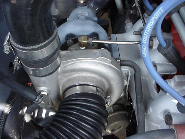
TO4B h-Trim Compressor/ T3 Stock Turbine Hybrid Turbo
I had my stock turbo upgraded and rebuilt by Performance Techniques. They put some funky paint on the turbine side that was black when I got it but had burnt off since. I recommend VHT paint instead. The compressor inlet uses the stock 2.75" hose and the outlet fits the stock svo/87+bird outlet piping. Here you can see how close the wastegate bracket comes to the ex. manifold. If you look closely, you can see where I welded on an extra piece of steel bent into an L-shape to the top end of the bracket to use the bolt hole there.
Engine Compartment
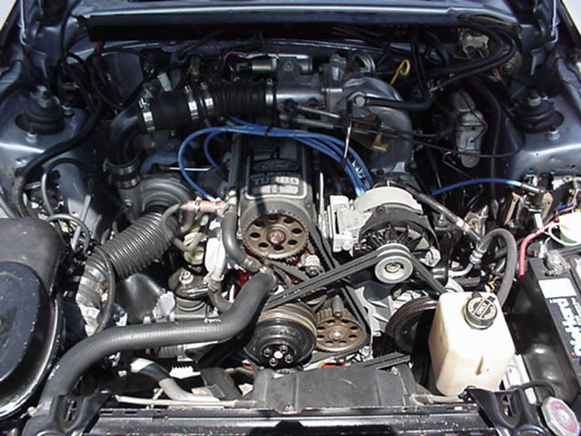
Engine Compartment Before I Installed the Spearco Intercooler
| 86 TC page | 86 TC Picture Gallery | Tbird page |