| Here are pictures of my home-made one-power unit finder inspired by plans from the Graham Wood web site. The idea is to generate an illuminated target image on a viewing suface through which the observer can sight a celestial object, placing it in the eye-piece field of view. Use Wood's excellent web-site for step-by-step instructions. My tips below may save you some time and leg work. |
| CONSTRUCTION TIPS TIP # 1 - LED ASSEMBLY: In place of the "block" LED used by Wood (which I couldn't find), I found that a single 5,000 mcu red LED worked well. I wired and mounted my LED in a 2x3 inch project box with a fitted styrofoam frame (which I made from discarded toy packaging) on the face of the box to provide a removeable, smooth, flat border surface on which to mount the target mask. Be sure that the LED illuminates your entire target area. Wood moves his LED assembly on a curtain rail. I found small brass tracks and rods at a hobby shop for less than a dollar that serve the same purpose. TIP # 2 - POTENTIOMETER WIRING: The potentiometer and resisters recommended by Wood are available at Radio Shack. Follow these directions at your own risk, but this is how I did it. Connect the red lead from the battery pack to one end of the recommended resister. Connect the other end of the resister to the middle loop/post of the potentiometer (a separate length of wire will probably be necessary). Take another length of wire and connect one end to the LED's positive leg (the longer of the two legs) and connect the other end to one of the end loops/posts of the potentiometer. Run the black battery lead to the negative leg of the LED (the slightly shorter of the two legs), completing the circuit. Turn on the battery pack if it has an on/off switch and turn the potentiometer's stem. If the LED brightens when you want it to dim, simply switch the wire on the end-post of the potentiometer to the other end-post. TIP # 3 - FRONT SURFACE MIRROR: To create a front surface mirror, coat one surface of your small mirror with a paint remover/stripper that has the key ingredient Methylene Chloride in it. In my experience, paint thinner or mineral spirits lacking that ingredient do not work. It might be best to do the next steps in a large glass jar with a lid that screws on tightly. This will prevent the odor from pervading your place of abode, protect your health (you do not want to inhale this stuff), and help you stay married a little longer. I used a glass jar with a plastic lid and kept it outside for good measure. A short soaking in the stripper should loosen any plastic backing enough to allow you to pry it off without damaging the mirror. Then place the mirror face down in the jar, pour a liberal amount of stripper over the back of the mirror and allow it to soak, covered in the stuff, for 8 hours. After soaking, carefullly take the mirror out and run a steady, forceful stream of warm water over it to remove the stripper and facing. Blot dry with cotton balls. Take care not to scratch the mirror. TIP # 4 - CREATING TARGET CIRCLES: The target can be made on a computer program. This was my first time working with computer graphics and I found smartdraw.com, which you can download and use free for 30 days, to be simple and user-friendly. Their support staff is very helpful and can walk you through the steps of creating concentric circles for a target. You must first know the size of your target circles. You will compute the sizes through some easy math that Wood assumes you know. I'll assume that like me, you have forgotten whatever basic triginometry you used to know. Here is how to calculate the size of the target circles (not crosshairs) for the mask size recommended by Wood of 1/2, 2 and 4 degrees. The formula given by Wood is: Diameter = tan(apparent size in degrees) x f where tan is tangent, apparent size in degrees is the size of a given target circle, and f is the focal length of your lens (from the magnifying glass). Now, check out these tangent tables to get the tangent of any circle. Let's say you're doing the calculation for the 4 degree circle first. So, checking the tangent table for a 4 degree circle you will see the number .0699. Multiply that times the focal length of your lens, say 8 inches if you're going with one of the sizes recommended by Wood, and you get a diameter of .56 inches. Convert to millimeters if you prefer. Do this for the other target circles, work with smart draw to create the target (white rings, black background), put several on a page (so you have extras and can relax if you ruin one or two while fooling around with assembly), print it, and bring it to an office supply store like Kinkos or Staples where they can make a good transparency for less than a dollar. Specify laser printing as opposed to ink-jet, as the latter has the potential to run if it gets wet. Parts List. Click here or go to next page. LINKS TO OTHER FINDER SITES: A Reflex Finder Photos of another finder inspired by the Graham Wood website A Unit Power Finder An award winning design A Simple LED "Red-Dot" Finder A creative low-tech alternative Herschelian Reflex Finder Inspired by the Tele Vue Starbeam Using a Daisy Electronic Point Scope on your Telescope How to modify a Daisy sight |
DESCRIPTION I built my finder from a 4 inch diameter map tube I had under my desk. You can use anything you like for a housing. My choice was based on availability and symmetry with my telescope. Components cost a total of about $20.00. The viewing screen is a sheet of 4x4 inch plexiglass called Acrylite. This has much better optical properties than regular sheet plastic or a CD jewel case. I think it is sturdier and makes for easier viewing than the cellophane used by Wood in his orginal finder. The on/off dimming knob, LED, battery case and project box are all from Radio Shack. The white mounting plate is called a universal bracket which I got at Radio Shack. The piece you see has adhesive and screws to affix it to the bottom of the finder. The correspondng male piece attaches to the OTA of the telescope in the same way. The 2 inch lens was taken from a magnifyiing glass and fits very nicely into the plastic lid of a six ounce Cremora container that I cut and trimmed with an exacto blade. The mirror is a 2 1/2 x 3 1/4 inch Connair mirror found at Linens 'n Things. Similar mirrors are available at pharmacies and discount chains. I mounted the mirror on a 2 inch diameter dowel I cut at a 45 degree angle. I saved a little bit of work by using the remainder of the dowel I had cut at 45 degrees for the secondary mount in my telescope). The interior project box with the wiring and LED are mounted on a set of brass tracks made from metal rod and track (check out a hobby shop). The outside is finished with monokote (left over from my telescope). The tube is trimmed at one end with black and chrome car-door molding from Trak Auto. The other end is sealed shut with a plastic lid from a food product that happened to fit. |
 |
 |
 |
 |
 |
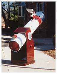 |
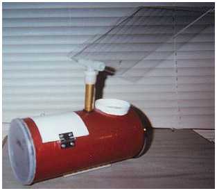
| The completed finder. The view-plate, a 4x4 inch piece of acrylic, is held in place by a plumbing tee with a 5/8 inch inside diameter that fits pefectly over the brass tube. I cut a slit in the tee to hold the plate and am able to adjust its angle with a small screw. The brass tube telescopes out of a short 21/32 inch diameter tube glued into the finder's body. A simple O-ring, snugly fit on to the smaller brass tube, holds the tube/plate assembly at the desired height. |
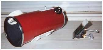
| Finder attached to my home-made 8" F7 Dob. |
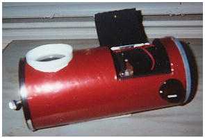
| The potentiometer/dimming knob on lower right is important to ensure that LED's intensity does not wash out stars. |
| I cut a small door in the tube for access to the battery pack (4AAs), potentiometer, and LED assembly. Thumb screws protruding from the open end adjust mirror angle (more detail below). |
| Universal mounting bracket on bottom of finder (left) mounts finder to telescope. Front-surface mirror (right) is mounted on a dowell cut at a 45 degree angle. Thumb screws allow adjustment of mirror. |
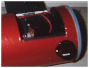 |
| In this close-up you can see the LED mounted onto a circuit board in the 2x3 inch project box. |
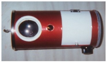 |
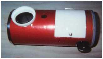
| This is a view from the top. The reflection in the lens is from the front surface mirror, mounted inside at a 45 degree angle. In the center of the finder tube you can see the 21/32 inch diameter tube which holds the view-plate assembly in place. |

|