This page from the "Stirling Engineer's Notebook" is intended to become an electronic alternative to the printed version of "Stirling News" - The Journal of the Stirling Engine Society. I will endeavour to get most of the text and illustrations reproduced in the printed version of Stirling News. There will be new pages added to the site on a quarterly basis.
sorry - still under construction
A Stirling engine is a machine which converts heat energy into mechanical power.
In its simplest form you could burn some wood and pump water or generate electricity to run a PC for example. A wood powered computer - that's a novel idea!
Stirling engines belong to a category of heat engines known as external combustion engines. This means that the fuel is burnt outside of the engine cylinder - rather than inside the cylinder. Steam engines are another example of external combustion engines. The other type of engine is more familiar- the internal combustion engine - the best example being the engine in a car.
External combustion has certain advantages - you can use any fuel which you may have lying around, like wood waste in a sawmill, coffee bean husks, maize cobs, domestic refuse as well as the more usual gaseous and liquid fuels. Solar power is also viable.
The other advantage is that you can control the amount of oxygen used in the combustion, and use the correct amount to get 100% combustion, which minimises the polluting waste products which occur during incomplete combustion.
Stirling engines will work off any source of heat, so do not necessarily need combustion of fuel. Successful Stirlings have been demonstrated running on concentrated solar radiation, or the waste heat from industrial processes, such as glass making or steel smelting.
Model Stirling engines are relatively easy to build, even out of bits of junk such as old tin cans or plumbing fittings.
Low temperature difference (LTD) Stirlings will even run on the heat from your hand - sadly they do not produce much power.
Stirling engines have been built in every size and shape imaginable from a tiny engine which will fit in a matchbox to an 800hp V12 monster intended for marine propulsion.
Unfortunately, Stirling engines are not really suitable for putting into cars, unless they are used as in electric hybrid mode.
There have however been Stirling powered vehicles, cars, buses, trucks and boats were all demonstrated in the 1960s.
.
RedRok -Alternative Heat Engine Site
White Cliffs - a diesel engine converted to solar steam power in NSW. 21.9% efficient using steam at 450 centigrade.
Pritchard Steam Power - Ted Prichard describes many years of steam car development
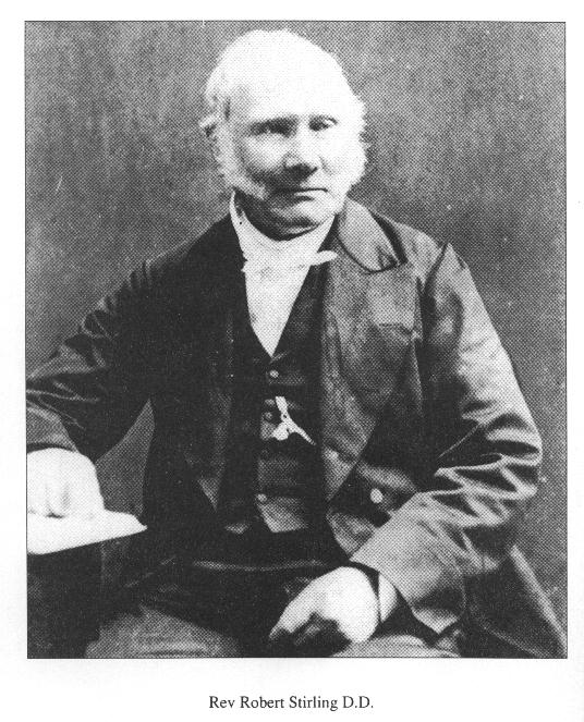
The Stirling cycle engine is named after the Reverend Robert Stirling who lived in Scotland between 1790 and 1878.
At the age of 26 he patented an idea for the reduction in cosumption of fuel (coal and wood) for any industrial process which required a substance to be heated and cooled - examples were in the glassmaking, pottery and brewing industries. He called this device the Economiser.
In addition to a general patent to cover any heating and cooling process he also citied the example of an air engine which ran on the repetitive heating and cooling of air, making use of a specific form of the Economiser to reuse heat within the engine. This meant that if some of the waste heat could be reused, then less heat would be needed in the first place - which is how you could save fuel.
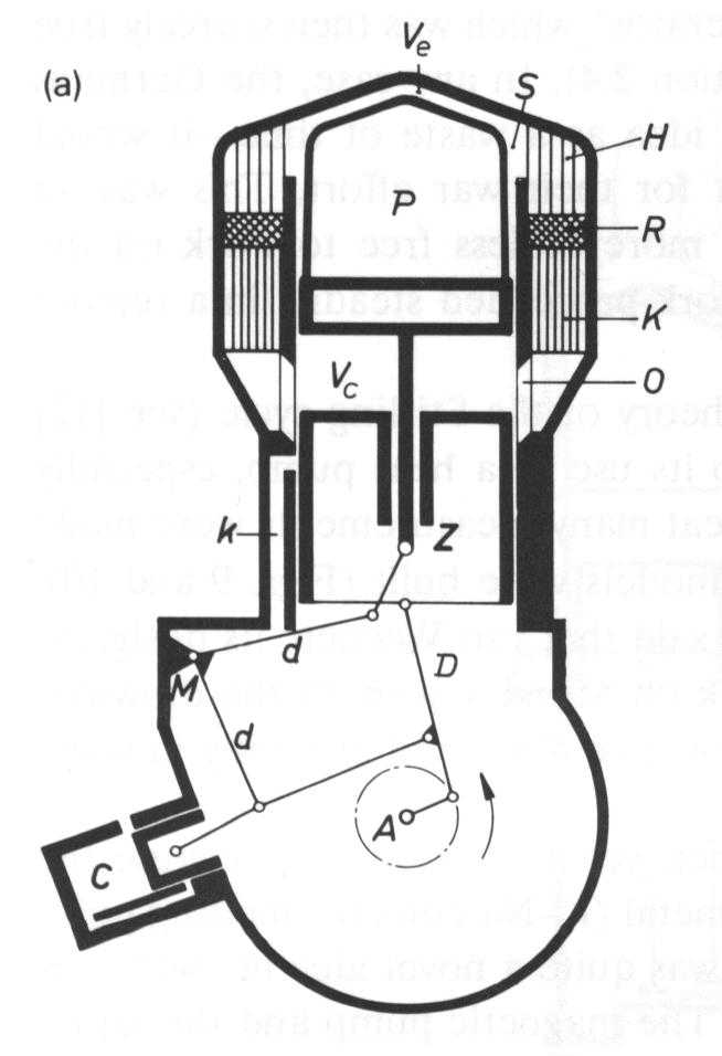
Stirling proposed an engine which contained two moving pistons, one being a loose fitting plunger known as the displacer and the other being like the piston in a steam engine with a leather sealing washer known as the power piston.
The displacer moves to and fro in a cylinder (the displacer cylinder) which is heated at one end and kept cold with water or air cooling at the other end.
The displacer is about three times as long as the diameter of the displacer cylinder, and about 3/4 of the length of the cylinder.
As it moves from hot end to cold end it displaces about 1/3 of its volume of air from the cold end to the hot.
In moving from the cold end to the hot, the air is rapidly heated and its pressure rises - if the displacer cylinder is connected to the power cylinder, the rising internal pressure will push the power piston outwards. The power piston is connected by way of a con-rod and crank or other linkage to turn the reciprocating motion into rotary motion.
As the power piston comes outwards pushed by the expanding air, the displacer begins to travel inwards thereby forcing the heated air down towards the cold end. Here the air cools and contracts causing the internal pressure of the engine to fall below atmospheric pressure. The power piston is therefor pushed back inwards by atmospheric pressure.
The displacer is also connected by way of a linkage to the crankshaft, and this causes it to shuttle to and fro as the crank turns. The linkage is so arranged so as to make the displacer reach the top of its stroke - the hot end, 1/4 of a revolution before the power piston comes to its top dead centre position. It is this 90 degrees phasing relationship between the displacer and the power piston which is key to the Stirling cycle operation.
Robert Sirling could see that because the air was being repeatedly heated then cooled, that most of the heat input at the hot end was coming straight back out at the cold end and heating up the water. He proposed, then demonstrated that by putting his economiser in the passage between the cold end and the hot, that some of this otherwise wasted heat would be retained and used later therby making the engine more efficient.
Here's the first of a series of simple experiments you can try at home to get yourself started with Stirling engines.
Some of these experiments involve heat sources, electric lightbulbs, tin cans with very sharp edges etc so if you are in anyway unsure of your abilities please do not try any of these experiments without assistance. I take no responsibility for the outcome of the expeiments described below.
1. The expansion and contraction of air.
The next time you finish a plastic polythene bottle of milk when making coffee, empty the milk out and pour in about a 1/2" depth of boiling water straight from the kettle. Put the lit back on and give it a quick single shake. The square sided bottle will swell up like a barrel as the air inside is heated by the boiling water.
Release the screw cap (pour the milky water into your coffee or down the sink) noting the hiss of the rapidly escaping air. Then put the cap back on tightly. As the air inside begins to cool down to room temperature, its pressure falls and the sides of the milk bottle will start to collapse inwards - forced in by atmospheric pressure.
When fully cold, release the lid and again notice the hiss of air - this time rushing back into the bottle.
Conclusion. Air expands when heated and can do work against the sides of a containment vessel in an attempt to keep the pressure constant. When cooled the air contracts, its pressure falls and atmospheric pressure will do work against the vessel in an attempt to equalise the pressure on each side.
The ideal gas law states that p x V/T = K (a constant)
Where p is pressure
V is volume
and T is absolute temperature
In the milk bottle experiment we perhaps increase the temperature from 300 Kelvin (27 C) to 330K (57 C) . This increase in absolute temperature of 10% will cause the pressure to rise by 10%. Because the walls of the bottle are soft and flexible the pressure change causes an increase in volume.
You can repeat the experiment but use a balloon stretched over the bottle top. The balloon will expand with the increase in pressure. An expanding balloon or rubber membrane taken from a balloon or rubber glove can be used to make a simple hot air engine.
Daniel Lyonnet, a good friend from Paris, shows how to build his ASAP engine using a beer can some balsa wood and a balloon.
The Stirling Engine Society was founded in January 1997, but existed in a somewhat unofficial from 1995. The society was formed by a group of model engineers and other Stirling enthusiasts, who were keen to see the development of the Stirling cycle engine into an everyday item.
Stirling News is the quarterly newsletter sent out to all society members, and I edited the first 10 editions from January 1995 to Winter 1998.
If you are interested in becoming a member of the Stirling Engine Society please contact :
The Membership Secretary,
Stirling Engine Society,
P.O. Box 5909,
Chelmsford,
Essex. United Kingdom.
CM1 2FG.
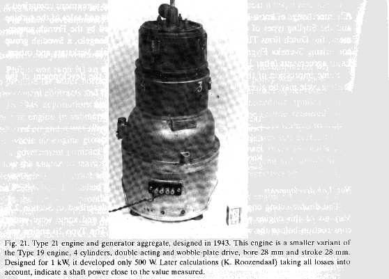
One of the key proponents in the recent development of the Stirling Cycle engine is Philips based in the Netherlands. Between 1937 and 1980 they worked on a whole series of Stirling projects engines and coolers for just about every conceivable end application.
An excellent book entitled "The Philips Stirling Engine" by C.M. Hargreaves - published by Elsevier covers the complete Philips story - well recommended.
The displacer system is one of the key assemblies in any Stirling or hot air engine and is a good starting point for experimentation. This constructional brief describes how to make one from empty tin cans. It can be used to investigate the expansion and contaraction of air and then build it into a working hot air engine.
The displacer has a 64mm diameter and a 25mm stroke so that it displaces 80cc of air. This will allow a power cylinder of 25mm to 38mm to be used again with a 25mm stroke. The displacer cylinder is of a size and type which is ideally heated by a 100W light bulb for convenience or even a nite-lite candle.
Electrical heating is preferred because you have a constant known power input, and even if you only get 1 watt of shaft power its very easy to calculate the thermodynamic efficiency of the engine. Once the displacer is assembled you can use a small geared motor and a con-rod assembly to cycle it up and down at different speeds. A pressure gauge can be used to measure the internal pressure swing. A useful rev-counter can be made from a cheap cycle computer - see below.
If you have access to an electronic pressure transducer and interface for a PC then it is possible to plot on the screen the cyclic pressure swings.
I am currently investicating the cheapest method of obtaining a suitable pressure gauge. I have noticed electronic gauges in motor accessory shops which are economically priced - but these will use atmospheric pressure as their reference.
Anyone with suggestions on these lines -please drop me an email.
Whispertech of Canterbury, New Zealand.
Solo Kleinmotoren of Sindelfingen, Stuttgart, Germany.
Sigma Electroteknisk of Olso, Norway.
Lund University - useful background information
2 330ml steel soft drinks cans
1 300g steel fruit can
2 390g cat food cans
1 short length of 4.0mm bore brass tubing
1 length of 6mm OD brass tubing - should slidefit over above tube
1 100mm length of 4mm brass studding with spring washer and nut to fit
Solder and flux
Tools - 25W soldering iron or small blowtorch, tin snips, modelling knife, compasses or dividers
Notes on using tin cans.
Steel cans are usually coated to prevent them rusting. This coating needs to be removed with emery cloth or steel wool Before attempting to solder. Believe me - I've tried it.
The inside of Pepsi cans may look like clean metal but it is reeally a transparent lacquer.
When cutting steel cans use the utmost of care - possibly even invest in some light duty work gloves - those edges are very sharp.
When soldering use a large soldering iron - of at least 40W and plenty of flux.
Alternatively use a micro-blowtorch for extra heat. These are quite cheap now and run of refillable butane canisters - lighter fuel.
Soft drinks - (particularly Pepsi and Tango brands) are sold in deep drawn steel cans of roughly 64mm in diameter (2.5"). The steel can is very thin so it has a low thermal mass and heat travels slowly from one end to the other. Steel can also be effectively soldered using ordinary soft solder and modest amounts of heat - so fabrication is relatively simple.
The following outlines a displacer system which is the heart of an electrically heated Stirling engine model which can be built quite easily from readily available items.
For the displacer find two steel drinks cans and cut them down to a height of 50mm or 2". This is best done by partly filling them with water, putting them in the freezer for a couple of hours and using the ice as a temporary mandrel to stop the can collapsing when you cut it with a sharp modelling knife - watch your fingers - it will be very sharp. Next snip one open ended can into a series of strips about 10mm wide and 20mm long so that they can be inserted into the open end of the other can making a displacer of 75mm lon sealed at each end. Clean off any remaining paint and solder the two can ends together. The displacer uses the dished base of each can, so it will be quite rigid. We now have to mount it on a central displacer rod. This can be a bolt or a length of threaded studding or a bit of brass tubing or a piece of piano wire. Any diameter between 2mm and 4mm is fine, but it is best to keep it lightweight.
Locate the centre of the can and drill a 4.0 mm (5/32") hole. This will take the fixing bolt for the displacer rod. Find a 100mm length of 4mm brass studded rod and fit it through the hole and secure with a nut and spring washer. Tighten thoroughly then solder the inner nut head to the inside of the end plate to prevent it from coming out. . Solder the end plate back onto the cut down can, having cleaner off the paint with steel wool and used plenty flux. Put the displacer to one side.
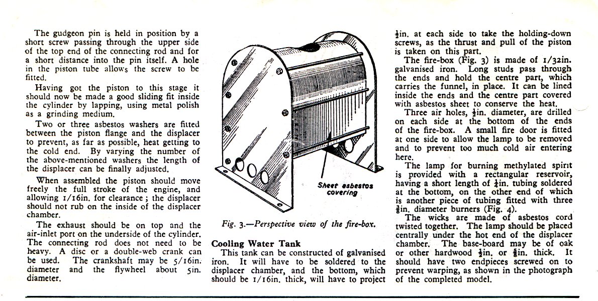
To make the displacer cylinder first find a 390g can - a catfood tin is ideal, or any one with the new style ring-pull lids. We need to make a disc to fit the end of the can from tinplate - possibly by cutting a disc from the end face of a larger can or just by using the end of a similar can which has had its end removed with a edge cutting can opener.
Locate the centre of the disc and drill a 4.8mm or 5/16" hole. Drill another 4.8mm hole 18mm from the centre. Find a 30mm length of 5mm bore brass tubing and solder this into the end of the can so that it is vertically upright - this is the gland and guiding bush to take the displacer rod. Use a 13mm length of brass tube and solder this into the hole offset from centre. This is the gas transfer tube.
Take a 100mm length of the 4mm bore tubing and clean up both ends to be free of burrs. Solder this vertically onto the protruding bolt on the displacer can.
Ensure the displacer is clean, free of paper labels or glue and airtight. Thread the displacer rod through the displacer gland and ensure that there is a smooth friction free fit. Place it in the displacer cylinder.
Perform a trial assembly of the displacer system and ensure everything is free running and not rubbing on the sides of the can. Finally, when satisfied, solder the end plate onto the displacer cylinder.
The displacer system is now ready for some action.
Initial Results.
I use a 100W light bulb as the heatsource for this size of displacer. It is not so hot that it will melt the internal soldered joints. To measure the pressure I use a U-tube manometer. This is a 2m length of 6mm bore clear plastic pipe, fitted to a wooden backplate with a scale attached. This simple bit of apparatus shows the pressure swings occuring in the displacer unit.
The first tests with the dispalcer heated up for 2 minutes over the lamp showed a water column swing of 300mm.
Twenty years ago I remembered a simple mnemonic for the pressure under a water column:
Probably Hairy Dogs Groom
pressure= height x density x gravitational constant
p = h x d x G
Where h is the height of the water column in metres
p is the pressure in N/m or pascals
d is the density of water 1000 kG per m3
and G is the acceleration due to gravity = 9.1 ms-2
Atmosperic pressure is about 100,000 Pa
What this all means is that it takes a pressure of almost 10,000 Pascals to support a column of water 1m high and standard atmospheric pressure which is 100,000 Pascals can support a water column of 10m or nearly 33 feet.
In terms of relating this to pressure swings, it means that the 300mm swing relates to a pressure swing of 5000 pascals.
In imperial units this is about half a pound per square inch.
Calculating the power of the Prototype
Simple engines like these will seldom produce more than a watt of power. In fact even a tenth of a watt is a good start for a first model.
Using the manometer to measure the pressure swing P, we then count the number of rpm which the engine revolves at N, and calculate the area of the piston A, and the stroke length L .
The Simple formula for the work done W is
W=P x L x A Joules
and the power output is the work done per second
Power = 2 x P x L x A x N/60
The 2 is because there is work done on both the outward expansion stroke and the inward compression stroke.
Power=PLAN
30
This should be quite easy to remember
On the prototype the piston is about 2.5sqcm so this experiences a force of 1.25N about 125g.
If the engine has a stroke of 30mm and turns at 300rpm then the power output will be
Power = Work in 1 second = 2 x Force x Stroke x RPM/60 Approximately!!
2 x 1.25N x 0.03m x 300/60 = 0.375W
For more information on tin-can Stirling Engines click the following link
Henry Kroll's Tin-Can Hot-Air Engine Page
To be continued with illustrations....................
The ability to turn heat energy into mechanical work is of fundamental fascination to me. Of course it is just one example of energy changing from one form to another - but the fact that it can be done with such simple machines is still quite amazing.
Stirling came up with 2 key innovations which made the hot air engine practical:
1. He developed the displacer design in a way which allowed air to be shuttled easily from hot space to cold space. He determined empirically the ratio of length to diameter for a displacer system being heated by a coal fired furnace.
2. The regenerator is an effective way of temporarily storing heat energy in a wire or gauze matrix in such a way that it can be reused on the next stroke of the displacer. This allows pre-heating of the compressed cold air as it is displaced from the cooler and on the return stroke it absorbs heat from the air so that it is already partly cooled befor entering the cooler. Less heat is required to be input at the hot end and less heat needs to be extracted at the cold end.
In my opinion the displacer is key to any hot air engine - it is the means by which a small amount of mechanical work used to move the displacer, can result in a large internal change in pressure and this pressure change can be used to do more work against a power piston. Some engines have a mechanical linkage to drive the displacer, but others like the Ringbom and Manson engines actually use the changing internal air pressure to drive the displacer directly.
The Manson Cycle Engine - Now Has It's Own Web Page!
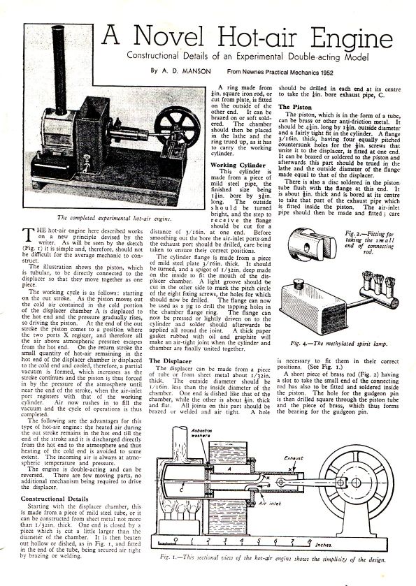
The Manson cycle engine has a displacer with a large diameter rod which acts both as the power piston and the displacer drive piston. The diameter of the displacer rod should be about 45% of the displacer diameter in order to get the most power from the engine. A Manson engine has only 3 moving parts and is analagous in this respect to a 2-stroke IC engine - and indeed a 2 stroke engine could be relatively converted into a Manson engine just by fitting a displacer to the top of the piston and providing suitable heater and coolers. Devised in 1952 by A.D. Manson, this engine is an interesting mix of open-cycle, Ringbom, and has hints of Ericsson and Lehmann in it. Detailed original article of the Manson engine can be downloaded by clicking
Manson Drawing 1.
Manson Drawing 2.
I have also written a quick Word document outlining the Manson engine and a Manson Engine simulator running in Excel - courtesy of Steve Truscott.
Low Tech Medium Temperature Engines.
I have also been a proponent of the medium temperature difference engine MTD. This is a low tech engine designed to run on little more than an open wood fire. As there is little chance of the hot end reaching the highest temperatures (650C) on a camp fire - I propose a modified hot end geometry so that most of the heat flow into the engine is through the top of the heater vessel. A 10" diameter cooking pot is used as the hot end, the displacer having a stroke of 3" to 4". The power cylinder would be made from a recycled automotive liner perhaps 4" in diameter. The slow turning engine would be intended for water pumping or generating perhaps 100W of electricity. See the following Word Article for details - Low Tech.
Modified Ross Linkage.
The Ross linkage is an ingenious way of connecting two piston rods in such a way that they are the necessary 90 degrees apart in phase. The original Ross linkage used a swinging arm to hold the centre point of the linkage in an almost straight line - however because of the radius of swing, one of the piston rods had a more linear motion than the other. This was used to advantage in that the displacer drive was given the linear motion and the power piston was fitted with a flexural joint which accommodated the deviation from vertical reciprocating motion.
The modified Ross linkage was one that I proposed to Roy Darlington in November 1996 and he incorporated it into the Double Gamma boat engine - now featured in Bob Sier's latest book.
The midpoint of the linkage is retained by a linear guide, in the simplest case a clevis joint fixes to the midpoint and a rod attached to it runs in a linear guide bush. The phase of this reciprocating rod is halfway between the displacer and the power piston and follows the crankpin in phase. The motion is similar to that of a crosshead or gudgeon pin driven by a standard crankpin and conrod. I have devised an Ross Link Calculator as an Excel spreadsheet to calculate the motion of this point for different lengths of arm and crank pin radius for the modified Ross link.
This central reciprocating point can be used to drive an air pump or water coolant pump.
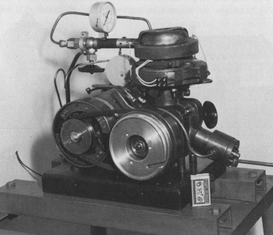
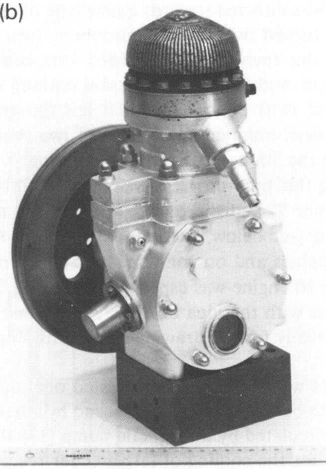
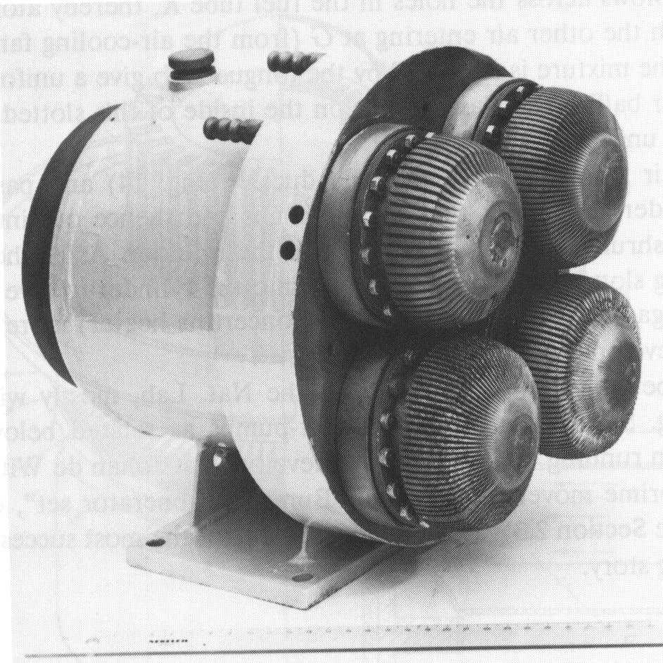
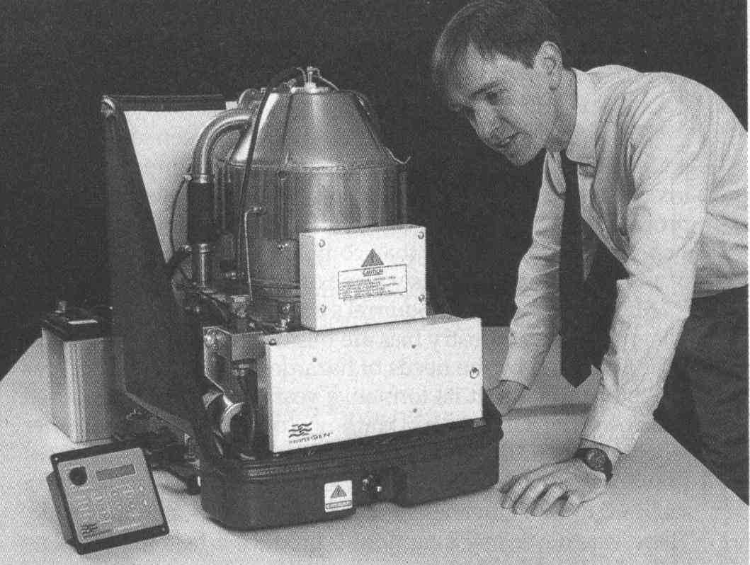
The Philips 102C "Bungalow Set" is a Stirling engine powered generator with about 100W of electrical output. It was produced in low volumes (estimates are from 50 to 150 units) in the early 1950's.
Many of these early uinits were given to Universities and Technical colleges and over the years were mostly forgotten, abandoned or cut into section.
Reading University had a 102C which they had heavily modified with new heat-exchangers fitted with thermocouples and pressure transducers.
This engine came into the possesion of my good friend Keith, and we had tried in the past to get it to run. Now armed with an extra powerful propane torch and a water cooling pump we thought we would have another go.
Originally the 102C was a very sophisticated set-up where a supply of compressed air was stored in the tubular framework of the gen-set. This was used to atomise the paraffin used in the burner, and a small pump on the side of the crankcase was used to recharge the reservoir when the engine was running .
Sadly much of this elaborate pressurisation system has been disabled or removed and we were faced with a mass of pipes and metric to imperial pipe fittings.
We quickly established that the crankcase would hold pressure, and that if you pump up the crankcase - the top end of the engine will receive a charge by leakage past the seals.
The replacement burner was not happy when connected to a bottle of propane and it refused to burn with anything other than a sooty luminous flame. I reckon that in the box of bits Keith had got from Reading, that someone had forgotten to pack the mixer tube. Instead we fashioned a crude cyclone burner from my blowtorch aimed at tangentially at the heater head and a sheet steel scroll shaped cover as a means of directing the blast right around the fins.
After getting the head up to temperature, it was a case of pull starting the engine with a piece of cord wrapped around the flywheel. With 50psi pressure in the crankcase, this usually brought the engine to life - sadly only to falter after 30 seconds or so.
Pausing for a cup of tea and some thought, we decided that there was not enough internal pressure in the engine for it to run with the heat we were supplying directly from the blowtorch. Instead there was excess head stored in the heater head and this was being consumed on starting, causing the engine to stall after some several seconds.
More pressure seemed the obvious answer, but my car footpump was incapable of suppling much more than 60psi and tended to leak if left connected to the engine. We also did not want the extra deadspace of the pump, connected to the working space, when the engine was running.
By half past four it was nearly dark, rather wet and getting windy. We decided to call it a day and wait untill I had got a compressor running so that we could charge the engine to its full working pressure.
I will keep you updated on how we get on with this vintage 102C Stirling Engine.
Click here for an article on the Early Philips Engines 1937 to 1953 as a 1.5MB downloadable Zipped Word file
For engines running below 1000rpm you can use this idea for a cheap and simple rev counter (Tachometer).
Buy a cheap cycle computer at your neighbourhood "Discount Store" for about $12.
Program the Odometer function with the value 167. When the magnetic pick-up is pointed at the magnet stuck to the flywheel, it will now read rpm/10 when the km/h speedometer function is selected.
eg. 657 rpm displays as 65.7 km/h.
For higher speeds (up to 2000rpm) program in 83 and then multiply the figure displayed by 2.
The magnet can be easily stuck onto and rotating steel part or use some sticky tape to hold it on.