
A Stirling engine is a machine which converts heat energy into mechanical power.
In its simplest form you could burn some wood and pump water or generate electricity to run a PC for example. A wood powered computer - that's a novel idea!
Stirling engines belong to a category of heat engines known as external combustion engines. This means that the fuel is burnt outside of the engine cylinder - rather than inside the cylinder like an internal combustion engine - the best example being the engine in a car.
External combustion has certain advantages - you can use any fuel which you may have lying around, like wood waste in a sawmill, coffee bean husks, maize cobs, domestic refuse as well as the more usual gaseous and liquid fuels.
The other advantage is that you can control the amount of oxygen used in the combustion, and use the correct amount to get 100% combustion, which minimises the polluting waste products which occur during incomplete combustion.
Stirling engines will work off any source of heat, so do not necessarily need combustion of fuel. Successful Stirlings have been demonstrated running on concentrated solar radiation, or the waste heat from industrial processes, such as glass making or steel smelting.
Model Stirling engines are relatively easy to build, even out of bits of junk such as old tin cans or plumbing fittings.
Low temperature difference (LTD) Stirlings will even run on the heat from your hand - sadly they do not produce much power.
Stirling engines have been built in every size and shape imaginable from a tiny engine which will fit in a matchbox to an 800hp V12 monster intended for marine propulsion.
Unfortunately, Stirling engines are not really suitable for putting into cars, unless they are used as in electric hybrid mode.
There have however been Stirling powered vehicles, cars, buses, trucks and boats were all demonstrated in the 1960s.
I have been interested in Stirling engines since 1976 when I saw my first hot-air engine in the scholol science lab.
My interest was rekindled in 1990 when I happen across an article in "The Engineer" describing a Stirling being built in Hampshire.
I strived to find out all I could and this eventually led to the formation of the Stirling Engine Society in 1997 -see opposite panel.
2016 is the Bicentenial of the patenting of the Stirling Engine. I hope that Stirling engines will be commonplace by then.
The Stirling Engine Society was founded in January 1997, but existed in a somewhat unofficial from 1995. The society was formed by a group of model engineers and other Stirling enthusiasts, who were keen to see the development of the Stirling cycle engine into an everyday item.
Stirling News is the quarterly newsletter sent out to all society members, and I was Editor for the first 10 editions from January 1995 to Winter 1998. Bob Sier has now taken over this role.
If you are interested in becoming a member of the Stirling Engine Society please contact :
The Membership Secretary,
Stirling Engine Society,
P.O. Box 5909,
Chelmsford,
Essex. United Kingdom.
CM1 2FG.
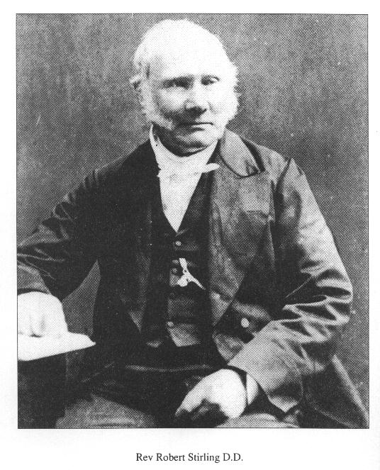
The Stirling cycle engine is named after the Reverend Robert Stirling who lived in Scotland between 1790 and 1878.
At the age of 26 he patented an idea for the reduction in consumption of fuel (coal and wood) for any industrial process which required a substance to be heated and cooled - examples were in the glassmaking, pottery and brewing industries. He called this device the Economiser.
In addition to a general patent to cover any heating and cooling process he also citied the example of an air engine which ran on the repetitive heating and cooling of air, making use of a specific form of the Economiser to reuse heat within the engine. This meant that if some of the waste heat could be reused, then less heat would be needed in the first place - which is how you could save fuel.
Stirling proposed an engine which contained two moving pistons, one being a loose fitting plunger known as the displacer and the other being like the piston in a steam engine with a leather sealing washer known as the power piston.
The displacer moves to and fro in a cylinder (the displacer cylinder) which is heated at one end and kept cold with water or air cooling at the other end.
The displacer is about three times as long as the diameter of the displacer cylinder, and about 3/4 of the length of the cylinder.
As it moves from hot end to cold end it displaces about 1/3 of its volume of air from the cold end to the hot.
In moving from the cold end to the hot, the air is rapidly heated and its pressure rises - if the displacer cylinder is connected to the power cylinder, the rising internal pressure will push the power piston outwards. The power piston is connected by way of a con-rod and crank or other linkage to turn the reciprocating motion into rotary motion.
As the power piston comes outwards pushed by the expanding air, the displacer begins to travel inwards thereby forcing the heated air down towards the cold end. Here the air cools and contracts causing the internal pressure of the engine to fall below atmospheric pressure. The power piston is therefor pushed back inwards by atmospheric pressure.
The displacer is also connected by way of a linkage to the crankshaft, and this causes it to shuttle to and fro as the crank turns. The linkage is so arranged so as to make the displacer reach the top of its stroke - the hot end, 1/4 of a revolution before the power piston comes to its top dead centre position. It is this 90 degrees phasing relationship between the displacer and the power piston which is key to the Stirling cycle operation.
Robert Sirling could see that because the air was being repeatedly heated then cooled, that most of the heat input at the hot end was coming straight back out at the cold end and heating up the water. He proposed, then demonstrated that by putting his economiser in the passage between the cold end and the hot, that some of this otherwise wasted heat would be retained and used later therby making the engine more efficient.
Here's the first of a series of simple experiments you can try at home to get yourself started with Stirling engines.
Some of these experiments involve heat sources, electric lightbulbs, tin cans with very sharp edges etc so if you are in anyway unsure of your abilities please do not try any of these experiments without assistance. I take no responsibility for the outcome of the expeiments described below.
1. The expansion and contraction of air.
The next time you finish a plastic polythene bottle of milk when making coffee, empty the milk out and pour in about a 1/2" depth of boiling water straight from the kettle. Put the lit back on and give it a quick single shake. The square sided bottle will swell up like a barrel as the air inside is heated by the boiling water.
Release the screw cap (pour the milky water into your coffee or down the sink) noting the hiss of the rapidly escaping air. Then put the cap back on tightly. As the air inside begins to cool down to room temperature, its pressure falls and the sides of the milk bottle will start to collapse inwards - forced in by atmospheric pressure.
When fully cold, release the lid and again notice the hiss of air - this time rushing back into the bottle.
Conclusion. Air expands when heated and can do work against the sides of a containment vessel in an attempt to keep the pressure constant. When cooled the air contracts, its pressure falls and atmospheric pressure will do work against the vessel in an attempt to equalise the pressure on each side.
The ideal gas law states that p x V/T = K (a constant)
Where p is pressure
V is volume
and T is absolute temperature
In the milk bottle experiment we perhaps increase the temperature from 300 Kelvin (27 C) to 330K (57 C) . This increase in absolute temperature of 10% will cause the pressure to rise by 10%. Because the walls of the bottle are soft and flexible the pressure change causes an increase in volume.
You can repeat the experiment but use a balloon stretched over the bottle top. The balloon will expand with the increase in pressure. An expanding balloon or rubber membrane taken from a balloon or rubber glove can be used to make a simple hot air engine.
Daniel Lyonnet, a good friend from Paris, shows how to build his ASAP engine using a beer can some balsa wood and a balloon.
Build Daniel Lyonnet's ASAP Engine -Click Here
The displacer system is one of the key assemblies in any Stirling or hot air engine and is a good starting point for experimentation. This constructional brief describes how to make one from empty tin cans. It can be used to investigate the expansion and contaraction of air and then built into a working hot air engine.
The displacer has a 64mm diameter and a 25mm stroke so that it displaces 80cc of air. This will allow a power cylinder of 25mm to 38mm to be used again with a 25mm stroke. The displacer cylinder is of a size and type which is ideally heated by a light bulb for convenience or even a nite-lite candle.
You will need
1 330ml steel soft drinks can
1 300g steel fruit can
2 390g cat food cans
1 short length of 3.2mm bore brass tubing
1 length of 4.8mm OD brass tubing - should slidefit over above tube
1 25mm x 3mm brass machine screw with spring washer and nut to fit
Solder and flux
Tools - 25W soldering iron or small blowtorch, tin snips, modelling knife, compasses or dividers
Soft drinks - (particularly Pepsi and Tango brands) are sold in deep drawn steel cans of roughly 64mm in diameter (2.5"). The sttel can is very thin so it has a low thermal mass and heat travells slowly from one end to the other. Steel can also be effectively soldered using ordinary soft solder and modest amounts of heat - so fabrication is relatively simple.
The following outlines a displacer system which is the heart of an electrically heated Stirling engine model which can be built quite easily from readily available items.
For the displacer find a steel drinks can and cut it down to a height of 75mm or 3". This is best done by filling it with water, putting it in the freezer for a couple of hours and using the ice as a temporary mandrel to stop the can collapsing when you cut it with a sharp modelling knife - watch your fingers - it will be very sharp. Next find a small tin can - 300g which has the old style rolled on ends. Cut one end off with an edge cutting can opener. This will make the end cap for the displacer. Alternatively the 300g can could be cut down and have its end refitted - but it is of a heavier gauge steel. Locate the centre of the end plate and drill a 3.2mm (1/8") hole. This will take the fixing bolt for the displacer rod. Find a 3mm brass machine screw and fit it through the hole and secure with a nut and spring washer. Tighten thoroughly then solder the head to the inside of the end plate to prevent it from coming out. . Solder the end plate back onto the cut down can, having cleaner off the paint with steel wool and used plenty flux. Put the displacer to one side.
To make the displacer cylinder first find a 390g can - cat food is ideal, or any one with the new style ring-pull lids. We need to make a disc to fit the end of the can from tinplate - possibly by cutting a disc from the end face of a larger can or just by using the end of a similar can which has had its end removed with a edge cutting can opener. Locate the centre of the disc and drill a 4.8mm or 5/16" hole.Drill another 4.8mm hole 18mm from the centre. Find a 25mm length of 3.2mm 1/8" bore brass tubing and solder this into the end of the can so that it is vertically upright - this is the gland and guiding bush to take the displacer rod. Use a 13mm length of brass tube and solder this into the hole offset from centre. This is the gas transfer tube.
Take a 100mm length of the 3.2mm bore tubing and clean up both ends to be free of burrs. Solder this vertically onto the protruding bolt on the displacer can.
Ensure the displacer is clean, free of paper labels or glue and airtight. Thread the displacer rod through the displacer gland and ensure that there is a smooth friction free fit. Place it in the displacer cylinder.
Perform a trial assembly of the displacer system and ensure everything is free running and not rubbing onthe sides of the can. Finally when satisfied, solder the end plate onto the displacer cylinder.
The displacer system is now ready for some action.
To be continued with illustrations....................
One of the key proponents in the recent development of the Stirling Cycle engine is Philips based in the Netherlands. Between 1937 and 1980 they worked on a whole series of Stirling projects engines and coolers for just about every conceivable end application.
An excellent book entitled "The Philips Stirling Engine" by C.M. Hargreaves - published by Elsevier covers the complete Philips story - well recommended.
The ability to turn heat energy into mechanical work is of fundamental fascination to me. Of course it is just one example of energy changing from one form to another - but the fact that it can be done with such simple machines is still quite amazing.
Stirling came up with 2 key innovations which made the hot air engine practical:
1. He developed the displacer design in a way which allowed air to be shuttled easily from hot space to cold space. He determined empirically the ratio of length to diameter for a displacer system being heated by a coal fired furnace.
2. The regenerator is an effective way of temporarily storing heat energy in a wire or gauze matrix in such a way that it can be reused on the next stroke of the displacer. This allows pre-heating of the compressed cold air as it is displaced from the cooler and on the return stroke it absorbs heat from the air so that it is already partly cooled befor entering the cooler. Less heat is required to be input at the hot end and less heat needs to be extracted at the cold end.
In my opinion the displacer is key to any hot air engine - it is the means by which a small amount of mechanical work used to move the displacer, can result in a large internal change in pressure and this pressure change can be used to do more work against a power piston. Some engines have a mechanical linkage to drive the displacer, but others like the Ringbom and Manson engines actually use the changing internal air pressure to drive the displacer directly.
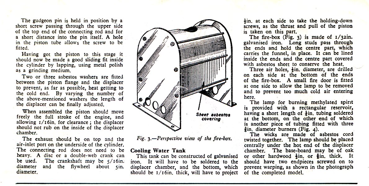
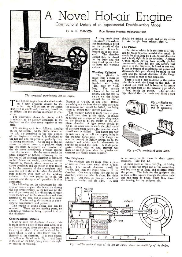
The Manson Cycle Engine
The Manson cycle engine has a displacer with a large diameter rod which acts both as the power piston and the displacer drive piston. The diameter of the displacer rod should be about 45% of the displacer diameter in order to get the most power from the engine. A Manson engine has only 3 moving parts and is analagous in this respect to a 2-stroke IC engine - and indeed a 2 stroke engine could be relatively converted into a Manson engine just by fitting a displacer to the top of the piston and providing suitable heater and coolers. Devised in 1952 by A.D. Manson, this engine is an interesting mix of open-cycle, Ringbom, and has hints of Ericsson and Lehmann in it. Detailed original article of the Manson engine can be downloaded by clicking
Manson Drawing 1.
Manson Drawing 2.
I have also written a quick Word document outlining the Manson engine and a Manson Engine simulator running in Excel - courtesy of Steve Truscott.
Low Tech Medium Temperature Engines.
I have also been a proponent of the medium temperature difference engine MTD. This is a low tech engine designed to run on little more than an open wood fire. As there is little chance of the hot end reaching the highest temperatures (650C) on a camp fire - I propose a modified hot end geometry so that most of the heat flow into the engine is through the top of the heater vessel. A 10" diameter cooking pot is used as the hot end, the displacer having a stroke of 3" to 4". The power cylinder would be made from a recycled automotive liner perhaps 4" in diameter. The slow turning engine would be intended for water pumping or generating perhaps 100W of electricity. See the following Word Article for details - Low Tech.
Whispertech of Canterbury, New Zealand.
Solo Kleinmotoren of Sindelfingen, Stuttgart, Germany.
Sigma Electroteknisk of Olso, Norway.
Lund University - useful background information
RedRok -Alternative Heat Engine Site
White Cliffs - a diesel engine converted to solar steam power in NSW. 21.9% efficient using steam at 450 centigrade.
Pritchard Steam Power - Ted Prichard describes many years of steam car development