1. For each pixel at location (xi, yi):
(a). compute its corresponding position in the other
image (x’i, y’i) using equations:
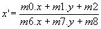 &
&  ;
;
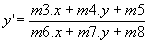
(b). compute the error in intensity between the corresponding
pixels, ei with equation:
 ;
;
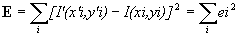
(c). compute the intensity gradient (
I’/¶ x’, 
I’/¶ y’) using bilinear
intensity interpolation on I’;
(d). compute the partial derivative of ei with
respect to mk using equation:
 ;
;
(e). add the pixel’s contribution to the Hessian
matrix, A and Intensity gradient vector, b with
components:
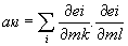 &
& 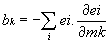 ;
;
2. Solve the system of equations,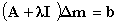 and
update the transform matrix estimate
and
update the transform matrix estimate
m(t+1) = m(t) + D
m.
3. Check that the error, E has decreased. If
not, increment l by a factor of 10
as described in [Press’92] and compute a new D
m.
4. Continue iterating until either the error is below
a threshold or a fixed number of steps have been completed.