JC's VCR-MULATOR
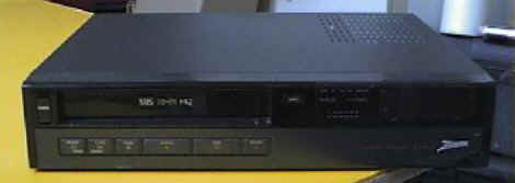
This is it! The photo above is my Emulation PC. I wanted to stay away from having a clunky PC and boards everywhere cluttering up my Entertainment Center. This is pretty incognito, don't you think?
Click on the thumbnails below to see how it all works.
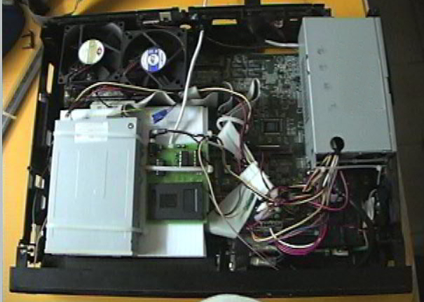 This is what it looks like inside...you can see most of the guts here.
Components include a slim-line power supply, AST P-60 motherboard with onboard
everything (I was going to add a tiny NIC, but the riser ended up being too much
of a pain to work around, so I scrapped that idea), two system fans to keep the
thing COOL, floppy drive and programmer on a corrugated plastic
"shelf" (which also acts as a duct for the air to flow over the
processor), COM ports - One wired into an RJ-11 phone jack to attach to the Emu
Board, and the other COM port is run out the back of the unit with a short
telephone wire (so that I can still access the programmer with my laptop without
removing it from this thing). Note that everything is powered from the PC
power supply, including an added Power indicating LED (Glued inside the
non-functioning "Power" switch). The Programmer is also powered
by the PC Power Supply, although I added a 3/4 amp fuse inline to the programmer
just in case some wires get crossed. Also included is an extension wire
from the red light on the programmer, which now powers a 2.1 watt LED that is
visible through the VCR-Mulator's clock window. This tells me when the
card is inserted wrong, and also flashes while the card is being accessed for
decryption while emulation is running. Also, there is a one-button
keyboard that is only capable of typing the letter "I". But,
that's all I need to type in order to shut down the unit safely.
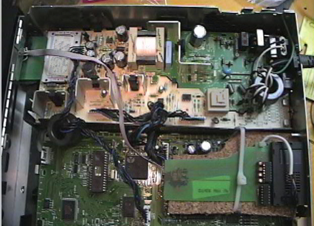
This is what it looks like inside...you can see most of the guts here.
Components include a slim-line power supply, AST P-60 motherboard with onboard
everything (I was going to add a tiny NIC, but the riser ended up being too much
of a pain to work around, so I scrapped that idea), two system fans to keep the
thing COOL, floppy drive and programmer on a corrugated plastic
"shelf" (which also acts as a duct for the air to flow over the
processor), COM ports - One wired into an RJ-11 phone jack to attach to the Emu
Board, and the other COM port is run out the back of the unit with a short
telephone wire (so that I can still access the programmer with my laptop without
removing it from this thing). Note that everything is powered from the PC
power supply, including an added Power indicating LED (Glued inside the
non-functioning "Power" switch). The Programmer is also powered
by the PC Power Supply, although I added a 3/4 amp fuse inline to the programmer
just in case some wires get crossed. Also included is an extension wire
from the red light on the programmer, which now powers a 2.1 watt LED that is
visible through the VCR-Mulator's clock window. This tells me when the
card is inserted wrong, and also flashes while the card is being accessed for
decryption while emulation is running. Also, there is a one-button
keyboard that is only capable of typing the letter "I". But,
that's all I need to type in order to shut down the unit safely.
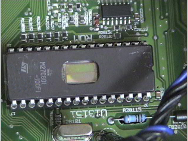
![]() Here you can see the power switch (turned on and off with the 'EJECT' button)
and the PCB from a dead keyboard which is hooked to the 'counter reset' button
behind an access door on the front of the unit. The PCB is plugged into
the keyboard PS2 port on the motherboard, there is one wire soldered to both the
4th and 12th edge-card contact on the PCB, and both wires are connected to a
very tiny switch which I ripped out of the guts of the old broken VCR.
When they are shorted by pressing the button, the letter "I" is
generated, as if from a keyboard, and the unit can be shut down safely.
Here you can see the power switch (turned on and off with the 'EJECT' button)
and the PCB from a dead keyboard which is hooked to the 'counter reset' button
behind an access door on the front of the unit. The PCB is plugged into
the keyboard PS2 port on the motherboard, there is one wire soldered to both the
4th and 12th edge-card contact on the PCB, and both wires are connected to a
very tiny switch which I ripped out of the guts of the old broken VCR.
When they are shorted by pressing the button, the letter "I" is
generated, as if from a keyboard, and the unit can be shut down safely.
![]() Cool BLUE LED Power indicator light...glows almost purple through the colored
lens of the old power button. I didn't really need this, but I couldn't
help including it. :)
Cool BLUE LED Power indicator light...glows almost purple through the colored
lens of the old power button. I didn't really need this, but I couldn't
help including it. :)
![]() Here you can see the ORANGE glowing LED that's hooked to what used to be a red
light on the programmer. Very handy when inserting the AUX card to know
that it's in right, and it also flashes when the Emu is running (as the card is
accessed). I think I will move this light over to the audio indicator
windows, as it will look more normal for light to be flashing from that area
while emulation is running. But, for now, it lives here. I want to
find a small (1" x 3" x 1/4" Max) Bright Red or Green LED clock
that I can put in the clock window, but so far, I have had no luck at all
finding anything even close. Everything is black on gray, and that just
won't do.
Here you can see the ORANGE glowing LED that's hooked to what used to be a red
light on the programmer. Very handy when inserting the AUX card to know
that it's in right, and it also flashes when the Emu is running (as the card is
accessed). I think I will move this light over to the audio indicator
windows, as it will look more normal for light to be flashing from that area
while emulation is running. But, for now, it lives here. I want to
find a small (1" x 3" x 1/4" Max) Bright Red or Green LED clock
that I can put in the clock window, but so far, I have had no luck at all
finding anything even close. Everything is black on gray, and that just
won't do.
![]() Here's the VCR-Mulator from the rear. You can see the RJ-11 Phone Jack
(COM 2), and the programmer's Serial Cable connected to the external extension
of COM 1. I could have kept this all inside the machine, but this way, I
can unplug the programmer from the VCR-Mulator's COM Port, and plug it into my
laptop (which sits nicely atop this PC), while the PC Power Supply powers the
programmer. Basically, I wanted to be able to use the programmer for other
purposes besides emulation without having to dig into this machine to get it
out, and this was the easiest way to do it. Works like a champ!
Here's the VCR-Mulator from the rear. You can see the RJ-11 Phone Jack
(COM 2), and the programmer's Serial Cable connected to the external extension
of COM 1. I could have kept this all inside the machine, but this way, I
can unplug the programmer from the VCR-Mulator's COM Port, and plug it into my
laptop (which sits nicely atop this PC), while the PC Power Supply powers the
programmer. Basically, I wanted to be able to use the programmer for other
purposes besides emulation without having to dig into this machine to get it
out, and this was the easiest way to do it. Works like a champ!
![]() I think this is the coolest part. The floppy and programmer are easily
accessible through the VCR-Mulator's Tape Door. :) I knew that thing
would come in handy for something.
I think this is the coolest part. The floppy and programmer are easily
accessible through the VCR-Mulator's Tape Door. :) I knew that thing
would come in handy for something.
 Here's the RCA DRD303RA that will be the VCR-Mulator's companion. Note
that all identifying markings on the unit have been digitally destroyed, so
don't waste your time, Dave! ;) I used part of an old Multi-Card PCB
I had laying around to use in the IRD's card slot. It's hooked into the
season/passive interface via a ribbon cable. The card slot of the
Season/Passive interface is easily accessible from a slot I cut in the back of
the IRD. Oh, and the IRD has a fancy new 303 Mod, too...just in case Dave
decides to kill my subbed bin. Oh, and the Emu's serial cable is also
hooked into an external RJ-11 Phone Jack.
Here's the RCA DRD303RA that will be the VCR-Mulator's companion. Note
that all identifying markings on the unit have been digitally destroyed, so
don't waste your time, Dave! ;) I used part of an old Multi-Card PCB
I had laying around to use in the IRD's card slot. It's hooked into the
season/passive interface via a ribbon cable. The card slot of the
Season/Passive interface is easily accessible from a slot I cut in the back of
the IRD. Oh, and the IRD has a fancy new 303 Mod, too...just in case Dave
decides to kill my subbed bin. Oh, and the Emu's serial cable is also
hooked into an external RJ-11 Phone Jack.
 Here's the 303 Mod - Photo again edited for security. Not much else to say
except here it is!
Here's the 303 Mod - Photo again edited for security. Not much else to say
except here it is!
![]() Here's the External RJ-11 Phone Jack and the Passive interface Card Slot...just
in case for some reason I don't want to emulate.
Here's the External RJ-11 Phone Jack and the Passive interface Card Slot...just
in case for some reason I don't want to emulate.
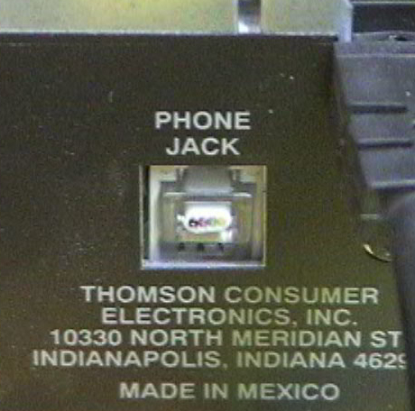 Just to make SURE no one ever plugs this IRD into a phone. Sorry, Dave...
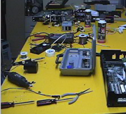 Lastly...the ole work table can get a little cluttered while you're hacking up
old VCRs and stuff. ;)
Lastly...the ole work table can get a little cluttered while you're hacking up
old VCRs and stuff. ;)
I Hope you enjoyed my pics! I have some other cool gadgets in my collection that I plan to add to this page. In fact, I think every single component of my Entertainment Center has something to do with hacking in one way or another. It is TRULY a Tester's Playground. :) Until then...
CLICK HERE FOR THE TUCKER 6 PROGRAMMER PAGE!
HAPPY TESTING!
