As an example of how this basic concept works, I modeled some drivers in Isaacs's Crossover Simulator (, using the FRD and ZMA files supplied for the Seas T25-001 tweeter and Vifa PL18WO woofer.
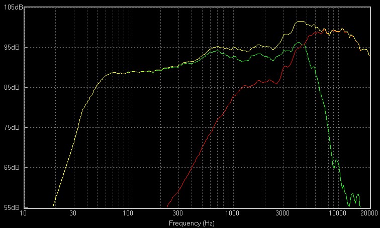
I first modeled a classic series crossover (ala Fig. A), using an 8
uF cap and a 0.42 mH coil. The result is shown in Fig. 1
(Note: This is for purposes of example ONLY, and the example series
network at Isaac's site was used to determine suitable node locations for
the various components. Note that I had to put some dummy components in
to make his example topology work. In order to make the output sum
well, the tweeter polarity was reversed.
With the ability to spatially align the tweeter location, and to achieve
proper 1st order series summing action, it should not be necessary to reverse
polarity on most real world projects. So lets agree to assume this
represents an idealized case with spatial alignment available, and the
tweeter does not have reversed polarity.)
Note that the final output curve would not be considered acceptable, and that it would normally be necessary to go to a second order series network to EQ the drivers enough to achieve some semblance of flat response. However, if we do this, the the advantage of the first order series network, that of good LBI performance, is compromised.
So by using the topology as shown in Figure C (minus the Zobel, this was a quickie, I strongly recommend the full topology of Fig. H), and using an R of 20 ohms, an L of 2.3 mH, and a C of 0.87 uF for the notch filter in series with the input of the classic first order series network, the excess energy from the top end of the woofer, and the excess tweeter level is brought down, and the drivers are also exposed to less drive level through that range of attenuation as well.
The result in Isaac's model is show in Fig. 2.
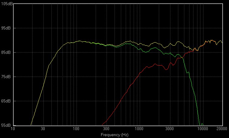
This is a pretty decent looking curve, and will have a uniquely clear sound due to maintaining a very good LBI for each driver. If proper spatial alignment of the tweeter and woofer is achieved, then this type of system will also be phase linear and transient correct.
These latter aspects may not be immediately apparent, but they follow from basic theory. Despite the use of EQ on the speaker system as a whole, the 1st order series crossover maintains time domain and transient correct performance AS IT IS EXPRESSED BY THE SYSTEMS AMPLITUDE RESPONSE, and so, when the FR is EQ'd to be nominally flat, the phase will follow and become more linear.
The use of this kind of LBI optimized crossover topology now allows one to use a much wider variety of drivers with a 1st order series network, and also provides a certain amount of readily tunable response, via the use of R4 in conjunction with R2. The mid band level can be brought up and down with ease, and a final choice of overall voicing selected without completely redesigning the whole crossover network.
In fact, this seems to be one of the side benefits of using an LBI optimized
topology, independent level adjustments that do not require recalculation
or redesign, but rather, can often be accomplished via a single series
or shunt resistor. As noted above, when using a second order parallel
network, and placing a single series resistor on the amp side of the circuit
(the parallel network's "input"), this can be adjusted for level, and the
main network components do not have to be re-calculated.
Cont'd
Link to page 4 of LBI Series Web Pages
All applicable copyright laws apply, all rights reserved, except transmission by USENET and like facilities granted. Any use or inclusion in print or other media are specifically prohibited. The informational content is not warrantied in any way or form, and any use of said content are at the reader's own risk, the author shall not be held responsible in any way for any damages or injuries arising from the content of this web site. Common safety practices are encouraged at all times. Do not fold, spindle or mutilate.