Now, what if we use the classic 1st order series network, with woofer Zobel, and we place any tweeter level pad or woofer EQ BEFORE the network, on the amplifier side of the series crossover?
We let the drivers do the 1st order series "forcing function" thing, and sum acoustically, with whatever rise in HF level due to a tweeter with higher sensitivity than the woofer, and we let the woofer HF rise happen, or any midband bump, and EQ it out before it reaches the series network portion of the circuit.
The acoustic result might have a broad midrange bump, with excess HF level, and would not look too great on a FR plot all by itself. So we put in some EQ via a series connected parallel notch filter.
Now for the basic series network with EQ and level pad capability, see
Fig. C. I show the simplest form first for simplicities sake.
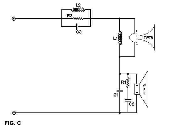
A good way of looking at this intuitively, is to think of R2 as dropping the level, and L2 as shunting the LF's around the level pad, and C3 as shunting the HF's around the level pad. These components, including the resistor, will need to be of the highest caliber, in order to not adversely impact the performance of the speaker system.
The resistor R2 will need to have a dissipation rating that is close
to equal to the full rated power of the speaker system, or it could begin
to limit dynamics due to heating effects, etc. Use of less dissipation
capacity here is not going to help things at all.
Like wise, the inductor L2 will need to have a low DCR, just as the
normal series woofer inductor, to maintain a low DCR at LF's.
The capacitor C3, and associated shelving resistor R3, and very HF
shunt cap C4, will all need to be very high quality parts, as these pass
the HF's to the entire system.
If you just wanted a tweeter pad only, then Fig. D shows how this would
be achieved. The pad level would be set by R2, and the point where
the padding was shunted would be set by L2. This is similar in topology
and concept to the use of a single series resistor in front of a 2nd order
parallel tweeter network.
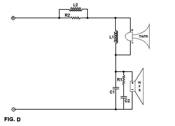
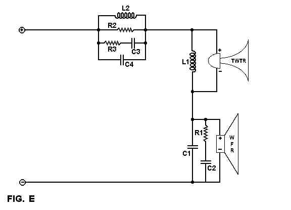
Fig. E represents the fundamental concept of maintaining LBI in a first order series network, while still allowing for the flexibility of padding the tweeter, and providing a certain amount of woofer EQ.
If the woofer had a bump at a lower frequency than the top of it's range, a separate parallel notch filter placed in series with the ground leg of the circuit, would allow for a separate EQ opportunity. Note that the two notch filters would be likely to interact with each other, and would require an iterative process of final tweaking.
See Fig. F

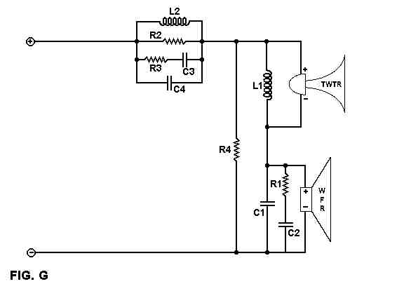
If we look at Fig. G, I have placed a shunt resistor across the basic
series network. This helps smooth the impedance the notch circuit
sees a bit, and provides a means of adjusting the overall amount of EQ
that occurs due to the EQ'd notch filter consisting of R2, L2, R3-C3 and
C4. This resistor (R4) might be on the order of 50-100 ohms, when
R2 might range from a few ohms to as high as 50 ohms for certain driver
combinations.
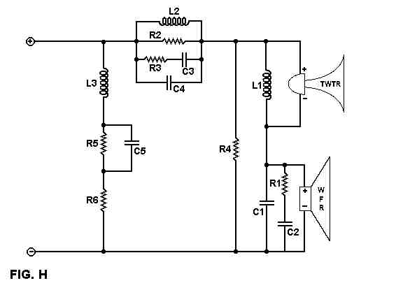
However, with the notch filter and/or tweeter level pad as in Fig. D, the impedance seen by the amp is NOT a flat resistive load. While this has often been ignored, due to the prevalence of low output Z amps, if a tube amp or SS amp with high output Z is used, the voltage divider formed by the speaker cable resistance and amp output Z, against the loudspeaker load Z will, cause a variation in the over all system FR.
Compensating the loudspeaker system input impedance to be as nearly flat as possible would greatly reduce these potential FR variations when a high output Z amp is used, and allow the use of any desired gauge of speaker cable without significant FR variation penalties as well.
For one way of doing this, see Fig. H. The idea is to match the
rise in impedance due to the EQ'd notch filter. Note that if a second
notch filter is used, that a second paralleled series filter may be required
to fully compensate the input Z of the speaker system.
I personally feel that this is a necessity with the high output Z amps,
and that it is not something that should be ignored or overlooked, regardless
of the actual crossover topology.
Cont'd
Link to page 3 of LBI Series Web Pages
All applicable copyright laws apply, all rights reserved, except transmission by USENET and like facilities granted. Any use or inclusion in print or other media are specifically prohibited. The informational content is not warrantied in any way or form, and any use of said content are at the reader's own risk, the author shall not be held responsible in any way for any damages or injuries arising from the content of this web site. Common safety practices are encouraged at all times. Do not fold, spindle or mutilate.