Parts Needed:
!. Factory Service Manual
2. Cruise Control Module with connector (94-96 B-body, L99 or LT1,
not sure about 91-93, but the connector from 91-93 will work)
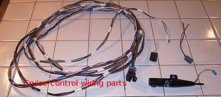
3. Multifunction Lever with cruise (any GM will do as long as it has
the short harness with connector. Pre-90's ones connect directly to the
steering column wiring)
4. Steering column harness under dash connector (Can be found on other
cars, but not sure besides 91-96 B-body)
5. Stoplamp connector 2 (any 91-96 B-body will have this. Not sure
about other models)
6. Wiring (all stranded): 22ft 20g dark green
22ft 20g dark blue
22ft 20g gray
22ft 20g brown
18ft 20g darkgreen/white
18ft 18g black/white
22ft 18g white
22ft 16g brown
7. Fuse box terminal and 10amp minifuse
8. 18g ring terminal
9. aprox 10 ft black plastic protective tubing (like you see all over
the engine compartment)
10. Tools and supplies for splicing and soldering
Factory cruise is something I've wanted since I had my 94 9C1 with original cruise. This was a great system and I was skeptical about using an after market system. It was rock solid steady only losing maybe 1-2 mph on steep hills and it had the tap up/down 1 mph feature. which combined with the certified digital speedo, made it very easy to control exactly how fast you want to go. As it was, it turned out that going factory was relatively cheap and I suspect easier than after market, since I was installing it in exactly the car it's designed for. This was not a trivial install, made harder for me because I don't have much experience with electrical work. A friend of mine is an electrical engineer, so he was able to advise me on general electrical questions, but he doesn't know anything specifically about cars. I didn't find anything on the internet and nobody on the 9C1 list came forward as having actually done this, so I was pretty much on my own. It's my hope that this page will make this project a bit easier for some other people. This page is not a step-by-step, but simply useful information I acquired.
When it was all done, taking it out for a test was nerve wracking. I was very scared it wouldn't work and I'd have to trouble shoot with the possibility that it could be my module itself. Let me tell you it was a great feeling when I set it and it held steady! Works just like my 94 did, and that's great.
This project can be broken into three phases: parts acquisition, planning and installation
I believe these parts are available new, though the two smaller connectors may be difficult to identify. They are not listed in the FSM 8A-202 section. Expect it will be more expensive than an after market cruise if you buy the parts new. The cheapest way by far is the junk yard route, but this took a lot of leg work for me. The easiest part was the module. I got it for $50 off an L99 civi car that I also got a bunch of interior parts from. Unfortunately, they wouldn't let me have the connector, or any other connectors, because they hoped to sell the whole front end wiring harness for a couple hundred dollars. Same with the turn signal lever, they wanted to sell the steering column intact. This is common with late-model junkyards. My local pick-your-own-part place happened to have the front half of an early 90's Olds 98, which had the correct turn signal lever ($10). This was fortunate as they hardly have anything newer than late 80's and they hardly ever have things like intact,clean turn signal levers. I also found a yard with the carcass of a 92 Caprice that I got the stoplamp connector from (that's about all that was left on the car!). The steering column harness connector I got at the pick a part by searching the steering column area of GM cars till I found one that looked right. I'm sorry I don't remember what car mine came out of. This is all a lot of work, but when you find that hard-to-find part, the feeling of accomplishment is great! It's like you struck gold or something.
The fuse box terminal I got from the dealer. Auto parts stores said they didn't have it. I'm sorry that I neglected to take a picture of it before I put it in. There are at least two types the dealer may have (or may not have, I couldn't get it till the third dealer!). Just look closely at your fuse box and get the one that looks right. The back side may look a little different, but the important thing is that the front side (where the fuse goes in) is the same.
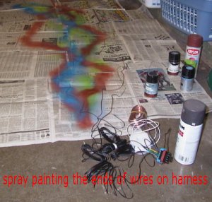
The wiring I wasn't able to get in the right colors, since I didn't know of a place that sold large selections of wire. For the 16g (power) wire, I used white. For the 18g's I used speaker wire. The 20g's I used all black wire and to keep the wiring from getting confused, I painted the last six feet or so the correct colors. Since I build model cars, I have lots of spray paints on hand. My electrical friend was able to loan me the soldering iron, heat gun and misc. soldering items, though I think between this project and the alarm and stereo installs, it would have been worth it to buy the tools. As Click and Clack say, every project is just an excuse to buy a new tool!
This project would be impossible without the FSM. Chilton/Haynes just won't cut it for this one. If you're not already familiar with the electrical diagrams, the first and most important step to take is to spend a lot of time studying 8A-34 until you understand it. These diagrams are very understandable to the layman, just read the beginning of the 8A section and it will tell you everything you need to know. After becoming very familiar with the cruise diagram, you should have a pretty good general idea what you'll need to do. One thing to note is to disregard the 39/85 cruise indicator wiring. This is for Buicks only (unless you're really ambitious and want to rig a light to tell you when cruise is on).
You'll probably say to yourself somewhere along the line, "why couldn't GM just have ONE wiring harness so you could just plug in whatever options aren't there?!" Of course they don't, they leave out the wiring on anything that isn't on the car to save a dollar a car and make our lives more difficult (they think we should just be buying new cars). There is one exception to this which makes this project MUCH easier. They do run cruise wiring through the steering column whether the car has cruise or not. This way all you have to do is plug in the wire from the lever and then find the other end sticking out amongst all the wiring at the end of the column.
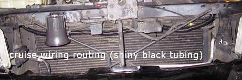
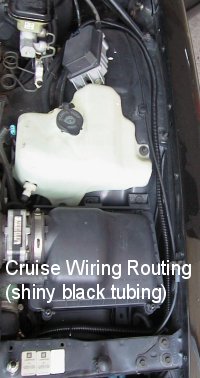
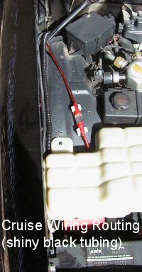
You'll want to scope out the routing for your wiring. Original cruise has the wiring going through the firewall behind the driver's side wheel well. This pass-through is very hard to visualize and even harder to get a hand into, from either side. They also have a fairly well fitting rubber seal on these pass-throughs. I decided to do it the longer but simpler route through the existing 1 inch hole the police drilled for wiring in the passenger side lower firewall. So the wiring had to go down the left side, across the radiator support, and up the right side, then across the dash. Sounds complicated, but I think it was easier than the stock pass-through. Most police cars have this hole drilled, but if mine didn't, I think I would drill it. I also used it for alarm wires and stereo amp power wire.
If you're not into soldering, you could get it done by crimping. But
any expert will tell you that soldering is the way to go for solid connections
and longevity. It also makes for a clean looking job. If you cover all
your connections with shrink tubing, it gives it a neat, professional appearance.
This is especially true at the cruise module connector. You'll have 8 connections
there and you'll want to cover them with protective tubing. Crimp-ons would
be very bulky there. Anyway, my advice is to bite the bullet and
do it right.
This is the order I did things. It's not an exhaustive list of every step I did.
1. Mounted module. Holes already exist on the wheelwell near the brake
master cylinder. The throttle link is very easy to attach. FSM will
tell how to do it.
2. Mounted Multi-function lever. Again, very easy and the FSM tells
how.

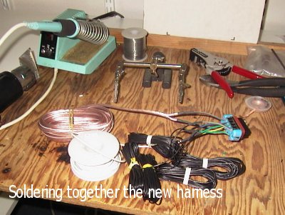
3. Made homemade wiring harness. This consisted of cutting the wires
to length, soldering them to the connector, painting the ends and taping
them together in a bundle. I actually cut mine to 20 feet, since
I need 5 black wires and bought a 100ft spool. I recommend 22ft because
it was quite close at the end and you could end up going a slightly longer
route. I had to extend one wire to get to the fuse box. You can cut off
any extra you have at the end.
4. Routed wiring in the engine compartment. Running through the firewall
hole, I extended the protective tubing into the hole to protect the wire
from the edges. A rubber grommet is also recommended for this. At this
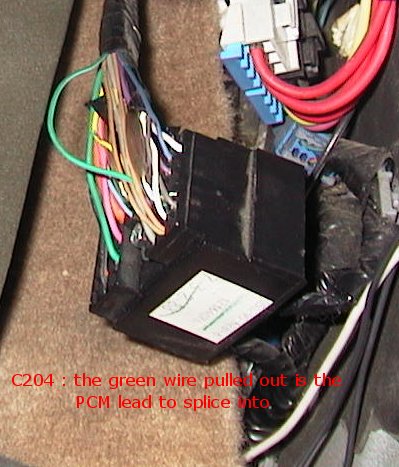
point you can stop off and make your first two connections to the PCM lead
in C204 and to the ground. This is a good place to do the ground. There
is a nice ground point below C204. This what the 18g ring terminal is for.
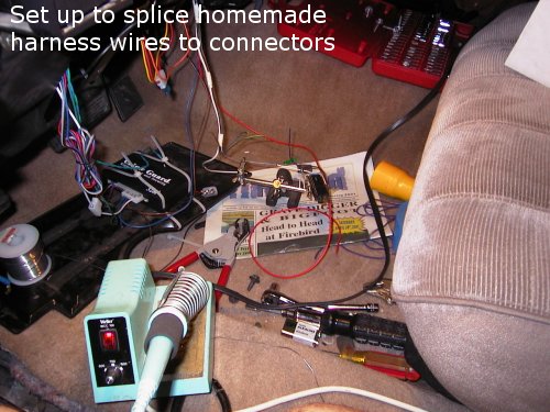
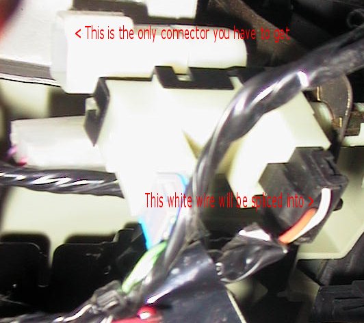
5. Ran wiring over to the steering column area. This is were I spliced
the remaining wires to the connectors. If you make yourself a little
work station on the floor, it's not too hard. The only hard part is splicing
the G wire into the white A wire on the Cruise Control Release Switch C2.
You can take out the connector, but you still have to pretty much splice
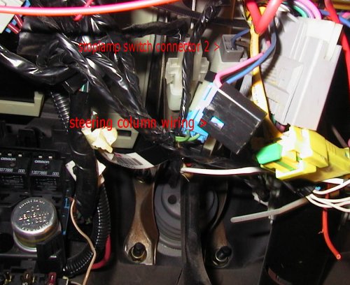
it where-is. One tricky thing for me was that the Stoplamp C2 wasn't
labled A and B, and the FSM lists brown and brown as the wire colors. It
figures they use a kaleidoscope of colors until it gets to the one thing
you have to differentiate! My connector had brown and blue anyway, so they
aren't even consistent! It was unclear if my wires were different gauges,
like the FSM says they should be. So I took an educated guess and turned
out right. The secret is that B is the upper wire (if C2 is to the right
of C1).
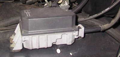
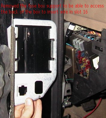
6. Then I just ran the F wire into the #16 slot in the fuse box. I took
the fuse box out from it's support, because I was in unfamiliar territory
and wanted to make sure I knew what was going on back there and get a good
look at the terminals. I think if you felt confident, you could probably
leave the box mounted and go in from underneath, especially since the 16
slot is on the lower part of the box. It is kind of tight and awkward under
there, though. Also, if your terminal is exactly like the original one,
you'll have to slide the white plastic retainer out. The base of my terminal
was narrower, though, so this wasn't needed for me.
Last modified 5/14/2001
email [email protected]