This paper will discuss the basic ray-tracing algorithm. It will also describe the concept
behind anti-aliasing, a method for improving the realism of an image by smoothing the jagged
edges caused by the digital nature of computer displays. This paper will not involve any
discussions of the more advanced features of today�s ray-tracers, such as motion blur, depth
of field, penumbras (soft shadows), texture mapping, or radiosity. Readers interested in
these more advanced topics are encouraged to refer to the books listed in the bibliography
section at the end of this paper.
This paper will begin by defining a "scene" and describing its basic elements. With this as
a foundation, it will then introduce ray casting, and then ray tracing as an extension of ray
casting. Finally, the paper will discuss the basic concepts behind anti-aliasing as a means
of improving the realism of an image, and will then conclude with a basic overview of how and
where ray tracing is used, as well as where to look for more information.
Although beyond the scope of this paper, it is important to note that all objects have some kind
of texture--a description of the way that the object looks. This includes the color of the object,
as well as any bumpiness, shininess, or design that the author of the image may wish to use. For
the purpose of this paper, however, and to simplify the discussion of how ray tracing works, we will
consider color to be the only texture present on the objects that will be described.
When a light source is defined, it is typically assigned, in addition to its location, an intensity.
This describes the brightness and color of the light. You might have a dimmer, red light in your
scene to give the effect of a dark room or a spooky atmosphere, whereas a bright, white light might
be used to give an outdoors-ish flavor to the scene. At any rate, lighting is considered by many
to be one of the most important factors in a ray traced image (Mosen). A picture flooded with too much light
might lose any sense of mystery you desired it to have, whereas an image that is too dark will not
show enough detail to keep its viewers interested.
A pin-hole camera is created by putting some film at the back of a light-proof box. A small hole
is subsequently poked in the front of the box with a pin, and the hole is covered with tape. To take
a picture, the camera is held steady and the tape is removed. Unlike a modern, high-tech camera,
however, the pin-hole camera must be left with the hole uncovered for a while, in order for enough
light to enter the box and strike the film (Glassner, 1-2).
An Overview of this Paper
This paper is intended to inform the reader of how the basic ray tracing algorithm works.
It will take a very simplistic approach to the explanation, avoiding the mathematical
perspective traditionally used by many books and papers on the subject. It is intended
primarily to inform the curious, rather than to teach the ambitious.
Scenes
Overview
In the context of ray tracing, a scene is a collection of objects and light sources that will
be viewed via a camera. Each of these items are arranged in what is called the world, or world
space--an imaginary place with height, width and depth (much like reality). For instance,
let's suppose that you wish to create an image of the earth and the moon. Your scene, then,
will consist of the earth, the moon, a light source that will act as the sun, and your camera,
which is where you are viewing this scene from.
Objects
In general, an object is any thing, either solid, liquid, or gas, that you will display in your
scene. A lamp, a glass of water, a planet, a cloud�any of these things can be objects.
Although ray tracers can only support objects that may be described mathematically (such as
spheres, cylinders, planes, cones, and so on), these objects may be combined in a variety of
ways to create more complex objects. For instance, a snowman is composed of three spheres, plus
a long cone for his nose, two more spheres for his eyes, and some arbitrarily situated cylinders
for his arms. Even very complex objects, such as computers, cars and spaceships may be created
this way!
Light Sources
Light sources, like objects, may be placed at arbitrary locations in the scene. However, unlike
objects, light sources emit light. They are thus key elements in any ray traced scene, since without
a light source to emit rays of light, there would be no rays to trace!
Camera
The camera (also referred to as the "eye" or "viewpoint") would be best introduced by describing how
a "pin-hole camera" works.
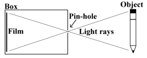 | |
In ray tracing, the camera is much like this in that it determines where on the "film" (or, in the
case of ray tracing, the computer screen) the light rays hit. The next section, "Ray Casting," will
explain in more detail how this is.
Ray Casting
Definition and Overview
Ray casting is a method in which the visible surfaces of objects (those parts of the scene that
are immediately visible to the camera) are found by throwing (or casting) rays of light from the
viewer into the scene. Although ray tracing is similar to ray casting, it may be better thought of
as an extension of ray casting. I will therefore begin the discussion of ray tracing with a
description of ray casting.
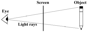 |
Light is represented on the screen in small, box-shaped units called "pixels." A typical computer monitor can support up to 1024 pixels horizontally and 768 pixels vertically, and sometimes even more. Each pixel may be assigned only one color at a time. In ray tracing, the color of a given pixel is the color of the light that passes from the object, though that pixel, into the eye (Hearn, 528). Each beam of light is called a "ray."
Rays
A ray is a thin, straight line used in ray tracing to model a beam of light. Although many people
like to think of a ray as the path of a particle of light, or "photon" (Glassner, 7), it is perhaps
more accurate to think of a ray as a single, long thread that starts in one place and extends in one
direction. For instance, in Figure 2 (above), the light rays are not individual particles, but are
rather straight lines extending from the eye into the scene. In many ways, it may help to think of
rays as little "feelers" or "tentacles" that reach into the scene to find out which objects are
visible at a given point. As such, rays become the foundation of any ray tracer, as will be apparent
from the description of the ray casting algorithm.
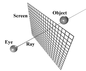 |
This is done for every pixel on the screen. You can begin to see here that this could take a long time
for complex scenes. For example, let�s say we are rendering (that is, ray tracing) a scene at a
resolution of 320 pixels wide by 240 pixels high, for a total of 76,800 pixels. Let it be of low
complexity, with only 20 objects. That means, over the course of creating this picture, the ray tracer
will have done 20 intersection tests for each of those 76,800 pixels, for a total of 1,536,000
intersection tests! In fact, most ray tracers spend the majority of their time calculating these
intersections of rays with objects. James Foley quotes Whitted on page 705 as estimating that anywhere
from 75 percent to over 95 percent of a ray tracer�s time is spent with such calculations! The good
news is, there are ways to decrease the number of intersection tests per ray, as well as increase the
speed of each intersection test. The bad news is, ray tracing complicates things much more than
simply ray casting does.
An example of infinite recursion appears in computer jargon. The acronym "GNU" stands for "GNU�s
Not UNIX" (Raymond). Since the acronym "GNU" refers to itself in the definition, it will expand
indefinitely if you were to repeatedly replace "GNU" with "GNU�s Not UNIX." For example, "GNU" would
become "GNU�s Not UNIX," which would expand to "GNU�s Not UNIX�s Not UNIX," which would again expand,
ad infinitum.
The ray tracing algorithm, too, is recursive, but it is finitely recursive. This is important, because
otherwise you would start an image rendering and it would never finish!
The algorithm begins, as in ray casting, by shooting a ray from the eye and through the screen,
determining all the objects that intersect the ray, and finding the nearest of those intersections.
It then recurses (or repeats itself) by shooting more rays from the point of intersection to see
what objects are reflected at that point, what objects may be seen through the object at that point,
which light sources are directly visible from that point, and so on. These additional rays are often
called secondary rays to differentiate them from the original, primary ray (Hearn, 529).
Often, in the literature about ray tracing you might come across the terms "backward ray tracing" and
"forward ray tracing." Unfortunately, both terms can be used to describe the same thing. Because the
standard ray tracing algorithm actually follows the path of light from the eye of the viewer backward
to the light source, it is, in that sense, often referred to as backward ray tracing. By the same token,
attempts to follow the paths of light from the light sources to the viewer are referred to as forward ray
tracing (Foley, 792). However, many authors assume that the practice of following light from the viewer
to the light source is the "normal" way, and may thus be considered moving in a "forward" direction.
They therefore refer to the practice of tracing from the light source to the viewer as "backward" ray
tracing (Watt, "Techniques", 221)! It is unfortunate that this serious ambiguity exists in even the most
scholarly literature about ray tracing. In this paper I will only refer to it as "ray tracing" and will
use it to describe the method of following the light from the eye to the light source.
In the following sections, I will describe the three major effects that may be achieved by ray tracing.
Each takes affect as soon as the ray is fired and the nearest surface that intersects that ray is found.
Ray Tracing
Overview
Whereas ray casting only concerns itself with finding the visible surfaces of objects, ray tracing
takes that a few steps further and actually tries to determine what each visible surface looks like.
Although it will cost your processor time spent in calculations, ray tracing allows you to create
several kinds of effects that are very difficult or even impossible to do with other methods (Foley, 782).
These effects include three items common to every ray tracer: reflection, transparency, and shadows.
In the following paragraphs, I will introduce the recursive nature of the ray tracing algorithm and will
show how these effects fit naturally into it.
Algorithm
Often, the basic ray tracing algorithm is called a "recursive" algorithm. Recursion is a means of
obtaining a result in which a given process repeats itself an arbitrary number of times. Infinite
recursion is recursion that never ends, and this is almost never useful. Rather, you need recursion
that will quit after a given number of loops.
Reflection
If the surface that the ray intersected was reflective, like a mirror, the ray tracer must determine
the color at that point by finding, not only the color of the surface, but also the color of the
reflection of any objects at that point. For instance, imagine a shiny wooden table. From where you
look at it, you will be able to see the reflections of objects on the table. This is because the
light from those objects travels to the table, bounces off it, and travels to your eye (Glassner, 13).
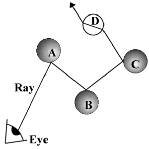 |
To model this with a ray tracer, all the program needs to do is calculate the angle at which the ray should bounce off, and then create another ray that will travel from the point of intersection in the calculated direction. Once that ray figures what color it needs to be (by calculating all the intersecting objects, finding the nearest one, and determining the surface color at the point, possibly even reflecting again), the first ray is then given that color. This is then propagated (or carried) back to the pixel through which the original ray was fired (Hearn, 529).
Some objects will bend light more strongly than others. This is determined by an object�s index of
refraction, which is a number that describes how fast light travels through an object as compared to
how fast light travels through a vacuum (Glassner, 134). Glass has a higher index than water, and will
this cause light to be bent more strongly than water. Similarly, lead crystal has a higher index than
glass, diamond has a higher index than crystal, and so forth.
Referring again to Figure 4, you will note the odd path that the ray takes through sphere D. In this
case, D is transparent, and the light is bent both on entering the sphere, and again on exiting it, just
as it would in real life.
Transparency
Transparency is modeled similarly to reflection, but instead of bouncing the new (or "spawned") ray off
of the surface, the ray is bent into and through the surface to model refraction. Refraction is an
optical phenomenon caused when light bends as it travels through a given substance. For instance, fill
a glass with water, and put a pencil in it. Looking from a bit above the glass, the pencil will appear
to be bent where it enters the water. This is refraction (Glassner, 134).
Shadows
Shadows are the third standard feature in ray tracing. Glassner gives a wonderful explanation of how
shadows are calculated in a ray tracer. Says he,
Imagine yourself on the surface of an object.... Is any light coming to you from the light sources?
One way to answer that question is simply to look at each light. If you can see the light source,
then there�s a clear path between you and the light, and at least some photons will certainly travel
along this path. If any opaque objects are in your way, then no light is coming directly from the
light into your eye, and you are in shadow with respect to that light. (Glassner, 10)
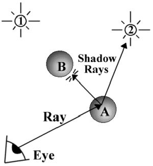 |
Figure 5 demonstrates how these shadow rays work. The figure shows two spheres (A and B) and two light sources (1 and 2). The ray travels from the eye to where it intersects with sphere A. In order to determine whether there is a shadow at that point, one shadow ray is fired at each light source. The shadow ray from A to the second light source travels uninterrupted, so light reaches the point from that light source. However, sphere B lies between sphere A and light source #1, so the point is in shadow with respect to that light source. The intensity of color at that point on sphere A would represent the fact that only one of the two light sources is shining directly on that point.
Analysis
As you can see, then, you pay for the increased features of ray tracing by a dramatic increase in time
spent with calculations. Not only must the program find all the intersections with the primary rays
(as in ray casting), but it must also find all the intersections for each secondary and shadow ray
(Watt, "Fundamentals", 162-63). Quality, in this case, is not cheap, and it only gets more expensive,
as you will see in the following section.
Anti-aliasing
 |
If you put a grid over the image and only color those squares that are entirely within the circle, you will get something like the following:
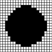 |
This blockiness is called "aliasing," and is exactly what happens when you try to display a circle on a computer screen. The problem may be assuaged somewhat by using a finer grid, like so:
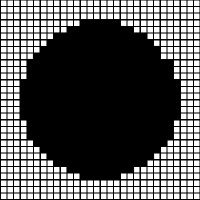 |
Still, the problem does not go away, and most people cannot afford to by the new hardware necessary to increase the resolution of their monitor (Glassner, 20).
Because of the digital nature of computers, it is not possible to completely eliminate aliasing. However, it is possible to minimize its effects, but not without a price. The solutions used by ray tracers today involve treating each pixel as a finite square area (which, in fact, they are), rather than as a mere point on the screen. Rays are fired into the scene through the centers of the pixels, and the intensities of adjacent rays are compared. If they differ by some pre-determined amount, more rays are fired into the surfaces of the pixels. The intensities of all the rays shot into a given pixel are then averaged to find a color that better fits what would be expected at that point (Hearn, 539).
[Note that the above description of anti-aliasing is conceptually accurate,
but for completeness' sake, Andrew Bromage
had this to add to the above paragraph: "... High-end renderers do not treat a pixel as a
square area, as this does not produce correct filtering behaviour. A pixel is not
a point, but it is a sample. Ideally, if the geometry of a scene is
changed even in a small part, EVERY pixel of the resulting image should
be affected. This is fairly counter-intuitive behaviour, but to see
why, have a read of Alvy Ray Smith's technical memo on the topic:
ftp://ftp.alvyray.com/Acrobat/6_Pixel.pdf"]
Continuing the above example, the anti-aliased circle might, then, be represented thus:
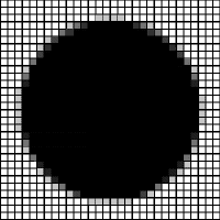 |
Anti-aliasing, then, helps eliminate jagged edges and to make an image seem more realistic.
[The following paragraph is not entirely accurate: Pixar did not use
raytracing in any significant amount to create the scenes listed below, but
rather used a sister technology known as "scanline rendering"--which does
not use the techniques described in this paper. However, one film which
did use raytracing extensively was "the Oscar-winning short film 'Bunny'
by Blue Sky Studios" (http://bunny.blueskystudios.com).
Thanks to Andrew Bromage
for the tip...]
Pixar, the makers of Disney�s hit movie Toy Story, list on their site quite a number of movies in
which they have used their software to create special effects. The list includes such hits as Apollo
13, Forest Gump, Jumanji, Terminator 2, and many more (Pixar). Clearly,
entertainment has a great demand for computer graphics.
There are many inexpensive ray tracers available, and some are even free. Appendix B at the end of
this paper lists several sites on the Internet where the reader interested in experimenting with ray
tracing might go to obtain a copy of any of several different shareware ray tracers. In addition to
the books listed in the bibliography at the end of this paper, the interested reader is also encouraged
to visit these sites to learn more about ray tracing and to find more in-depth explanations and tutorials.
Glassner, Andrew S. An Introduction to Ray-Tracing. San Diego: Academic, 1989.
Hearn, Donald. Computer Graphics. EngleWood Cliffs, N.J.: Prentice-Hall, 1994.
Mosen, Fabien. "An Image that Tells a Story." Online posting.
http://ourworld.compuserve.com/homepages/MichelMosen/story.htm (23 Mar. 1998).
Pixar Animation Studios. "Pixar�s Renderman." Online posting.
http://www.pixar.com/products/renderman/prod-info/rm_info.html#movies (23 Mar. 1998).
Raymond, Eric. "Recursive Acronym." The Jargon Dictionary. 24 Jul. 1996. Online posting.
http://www.netmeg.net/jargon/terms/r/recursive_acronym.html (23 Mar. 1998).
Rogers, David. Techniques for Computer Graphics. New York: Springer-Verlag, 1987.
Watt, Alan. Advanced Animation and Rendering Techniques. New York, N.Y.: ACM Press, 1992.
Watt, Alan. Fundamentals of Three-Dimensional Computer Graphics. Reading, Mass.: Addison-Wesley, 1989.
"The Mother of All Ray Tracing Pages."
http://arachnid.cs.cf.ac.uk/Ray.Tracing
Pixar Animation Studios. http://www.pixar.com
POVRay. http://www.povray.org
Blue Moon Rendering Tools (BMRT) http://www.bmrt.org
Conclusion
Ray Tracing in Industry
So, you might ask, just what practical uses does ray tracing have? David Rogers lists several,
including such things as "simulation of real-world phenomena for vision research, medical (radiation
treatment planning), seismic (density calculations along a ray), mechanical engineering (interference
checking), plant design (pipeline interference checking), hit-testing in geometric applications, and
impact and penetration studies" (Rogers, 174). However, ray tracing (and computer imaging in general) has
been especially widely used in entertainment.
Further Information
This paper has only just scratched the surface of the topic of ray tracing. In addition to the
primitive features of reflection, transparency, and shadows, most ray tracers today support different
texture mapping options, focal blur, radiosity, motion blur, and a host of other advanced features.
Appendix A: Bibliography
Foley, James D. Computer Graphics : Principles and Practice. Reading, Mass.: Addison-Wesley, 1990.
Appendix B: Web Sites of Interest
"Jamis� Hall of Ray-Traces." http://www.geocities.com/jamisbuck/gallery.html
Examples of ray traced images from my own personal gallery.
Provides information and links about other shareware and freeware ray tracers. Also has
links to other pages about ray tracing. [Note: this link appears to be broken by 5/17/99,
and I have not been able to locate it's new location]
One of the leading companies in computer graphics and animation.
The most commonly used hobby ray tracing program. It is completely free and available for most platforms.
A wonderful shareware rendering tool, available for most platforms. It is
fully Renderman(R) compliant (which means that it supports the same protocols
and features that the major commercial renderers do). What's more, it supports
all kinds of cool, advanced features like radiosity, NURBS, and programmable
shaders! Check it out!
Appendix C: Glossary of Terms