Homepage
Homepage
Here you will find the best homebrew MP3 Player the world has ever seen
;-)
Ok, a little more serious, it's a new member of the MP3@homebrew family.
Hier gibts das ganze auf DEUTSCH.
How was this amazing device created ?
Was it a gift from the almighty Lord?
It just takes
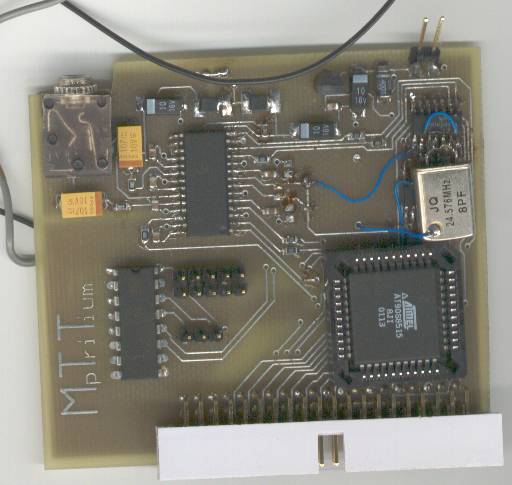
This is the Component side of the player. As
you can see, its a typical prototype with some minor modifications. More
on this later.
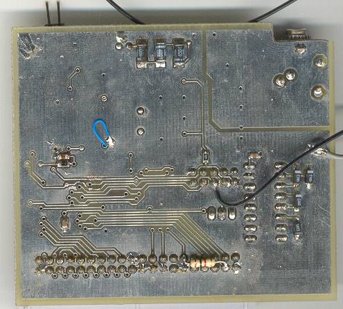
Here we have the Solder side, not that interesting
(exept for the guys who are trying to de-noise their players)
Nice, I would like to build this thing too, where the hell are the schematics'n stuff ??!!!
Schematics (gif 153 kb)
Layout, component side (gif 42 kB)
Layout, solder side (gif 41 kB)
Assembly Schematics (gif 33 kB)
Part list
Cables Schematics (gif, 85 kb)
TurboPascal Sourcecode
Player EXE (rename to MP3.exe, stupid geocities
:-(
Assembler Source
Hex file, ready to be programmed right
into your AVR (rename it to MP3_V01.hex, stupid geocities :-(
Everything archived (Pictures, Schematics,
Layouts, Eagle files, TurboPascal Sources and EXE; zip 448 kB)
OK, is there something more I should know ?
Hmm, I don't know. There is nothing special with this player, except the build in back door to get all your PIN, TAN, ID numbers to flush your bank accounts, enter your personal description into the FBI most wanted list. And not to forget the TNT time triggered pipe bomb.
NOOOOO, just kidding ;-)
Ok, to get a little more serious, here some comments about the design.
At first, this is no breadboard style point-to-point-chaos-wireing. A (more or less) good designed PCB with a solid ground plane for the digital part and a seperate ground plane for the analog part. This is very important to keep noise generation low (generated by the digital logic and outer sourounding noise sources) and to keep the incoupling of noise low. I wont explain the principles of noise coupling in detail, just a few words. Noise is generated (an coupled into circuits) mainly by current loops. If a signal wire forms a big loop (great area) with the ground plane (or ground wire), this structure will radiate (or recieve) a lot of noise. Keeping signals and ground close together, the loop area is minimized and so is the noise problem.
Another thing is power supply filtering. My player uses the suggested scheme from the VS1001 datasheet. And there is no (noticable) noise in the earphones. ;-)
The AVR is running on 5V, the VS1001 on 3V. To interface with 5V logic, all input of the VS1001 have series resistors to limit the current into the pin when it is driven by 5V (internal protection diode will clamp the input voltage to Vcc+0.7V, here somewhere around 3.7V). This series resistor in combination with the input capacitance of the IC are forming a RC-low pass filter, which slows down the signals. But here this is not critical, because the fastest signal into the VS1001 is the SPI clock with 1.5 MHz (except the 24 MHz clock). This is almost DC. ;-). For the 24 MHz clock signal, 1k is too much (RC-time constant too long), so it is just 100 Ohms.
Since the VS1001 internal Oscillator amplifier is famous for his disfunctioning, which I also learned the HARD way :-(, the oscillator is now formed be two free NAND gates. Works nice ;-) The 24.576 MHz clock is divided by 4 down to 6.144 MHz by the 4040 (12 bit ripple counter) and used as the AVR clock. When building this oscillator, make sure to get an fundamental mode crystal, an overtone wont work (without major modifications).
The ISP connector is pin-compatible (identical) with the original Atmel STK-200 plug.
The RS232 port is nice for debugging and control.
What's comming up next?
Thats all for now. If you have some comments, questions or would
like to donate a nice bottle Martini
;-), drop me a mail. ;-)
Last update: 04.10.2001