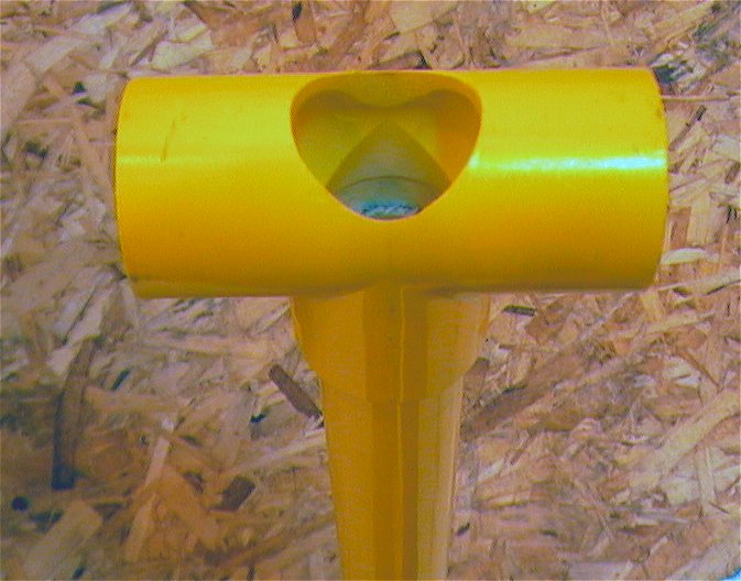
The three pics show the fill/pilot valve assembly which wiil be attached to the yellow 2" plug. The eight screws (12-24 x 1/2") hold the end cap in place on the 2" Tee.
1. The first pic shows the front view of the diaphragm There is a washer behind the screw.
2. The middle pic shows the back side of the diaphragm. It also shows the steel disk that prevents any flexing of the 3/16" 3-ply rubber diaphragm and allows it to seal against the barrel. Although the diaphragm material is fairly stiff, it would not seal without the steel disk backing. There is a lock washer behind the nut. The black line is just an alignment mark, which points to the top. This insures the diaphragm is installed in the same orientation every time. The equalization port, although not visible in the picture is about 20 degress to the left of the alignment mark. It will be enlarged to about 1/16" to allow quicker filling of the chamber.
3. The last pic shows the spring in its normal position. The yellow plug goes on top of the diaphragm assembly. Although the spring is "free-floating", there is some initial tension that keeps it in place. No other form of attachment was used. I have not had any problems with it shifting. Maximum movement of the diaphragm assembly does not cause coil bind-up of the 1 1/2" long by 3/4" spring. The outside of the diaphragm hits the end of the yellow plug, acting as a stopper, while the steel disk just clears it. The plug has been trimmed to 3/4" in depth. |