Back to Products' menu
Real time controller
Real time controller is a timer that operates outputs according to some conditions. These conditions can be either
time based operations, inputs' signals or both.
The main advantage of this controller is its high flexibility and low price.
The device is also very compact and can be
used for many applications.
The main schedule is stored within the controller as (hour, minutes, command). The controller has a real
clock and
systematically checks that the schedule follows the customer instruction. The instructions are an hexagonal number,
which has the capacity of switching on/off six outputs.
The controller has also 4 inputs, which can be configured to interfere with the schedule in order to perform
more compicated tasks.
The package RTC_D1 is presented on the figure 1 and 2. It is our simplest design.

Figure 1 Front_view

Figure 2 Back_view
The main unit is based on our prototype 'Miniature Real Time Controller': http//www.selectec-consultants.co.uk/r_t_c.html
The microcontroller unit can opperate upto 250mA devices. It has 6 outputs (relays or optocuples)
operating with 12V
and 4 inputs (close or open). The schedule can be stored on the chip (using a programmer) and the system has
to be restarted. It operates using a real time clock and can update the shedule every second.
The device is constructed from two compartments: front and back side.

Figure 3 Front view- interior
The front side, presented on Figure 3, is low voltage. It accomodates the microcontroller system and the
transistor's amplifier. Also this space accomodates the 12V power supply and the 5V regulated voltage
for powering different parts of the device.
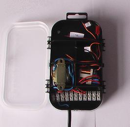
Figure 4 Back view- interior
The back side accomodates the high voltage devices such as relays etc... It has 4 big compartments (
excluding the
connectors and the transformer) for placing devices connected to each output. For example you can see on your
right side in the middle a
(Figure 4) small relay 220V/5A connected to the output. All inputs operate with 5V and they are situated
on the microcontroller
unit (green connectors on Figure 3) on the front side.
The only connection shown on the figures (the back cable) is the main supply for the device.
However, the device has 22 available high voltage connections (separate into two isolated compartments)
and 4 inputs connections. Every connected relay can have 3 outputs, so it can be configured as NO(normal open)
or NC (normal close) contact.
At the same time, some of the functionality (NO or NC) can be set softwarely using
different system configuration regimes.
The presented item is mainly designed for 220V devices and relays connected to the outputs.
However, because of
the special design construction, you can control opto-cuplers or other devices just by reusing the empty
compartments
from the box. It will be relatively save to accomodate high and low voltage devices in the back side, because
of
good isolation of the walls (plastic 1mm). If you need to open the front side to restart the device or replace
the batteries, it is save to do so during device operation. Please be carefull when opening the back side.
For savety reasons, it is recomanded this to be done only if the device is disconnected from the main.
For information abouth the microcontroller unit functionality please visit this site:http//www.selectec-consultants.co.uk/r_t_c.html
|