|

Back to Prototypes' menu
Miniature Real Time Controller
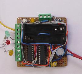
About the device in general
The main purpose of this device is to follow instructions (initially stored within the memory)
for switching different devices
in real time. The time schedule can be stored in the memory (part of the processor unit) as three bytes : hours,
minutes and output instruction. The device operates by comparing every second the real time and the table
with customer instructions. If a match is found the output will be activated following customer instructions.
The instruction for the output has to be presented as hexagonal value. The memory of the controller can accommodate
upto 20 instructions.
These instructions can be repeated after some period of time (24 hours or 168 hours).
This controller can not only trigger in real time outputs but also inputs. The device has four inputs, which can be
configured in different ways to trigger related output. The controller responds to the environment not
only by checking the time.
The microcontroller is very small (60x60mm) and flexible in terms of configuration.
It can replace mechanical timers in control systems, can be used for experimental equipment or for domestic use.
The timer can be reprogrammed up to 1 000 000 times without damaging the chip. It has an open collector
buffer protection, which
allows a current up to 40 mA to be used. The batteries (2x1.5V) allow the timer to operate even without supply.
The consumption in this
case is microamperes. This practically means that you do not have to replace the batteries for years.
When the supply is restored the controller, keeping the real time, carries on schedule powering the outputs.
Functionality
This device can power six outputs simultaneously. For each of the first four outputs it has a related input.
These inputs can be configured
to switch the output according to some signals. The device can operate in daily or weekly schedule.
Configuration flexibility
This device has 64 bytes EEPROM memory for storing the schedule plus the configuration instructions.
It uses the first 60 bytes to store the schedule in a particular format (hour, minutes, command). Bytes 63 and 64 are
used
for setting up the
starting time (after reset).
Byte 62 is a configuration byte that can configure the inputs and the schedule (24hour/1week)
Configuration
This controller is using EEPROM to store the configuration instructions on an address 00h-63h as follows:
- address 00h - 59h: if the mode is 24 hours:[ hours(decimal) minutes(decimal) output status (hex)] or if
the mode is a week:[hours(hex) minutes(hex) output status(hex)]
- address 62 and 63:It keeps the initial time after reset as: a)in case 24h mode :[hours(dec) minutes(dec)]
or b)if 1 week mode: [hours(hex) minutes(hex)]
- address 61 is port configurator and uses bits 0,1 and 2. If bit 0 is set, the output will be triggered only
in simultaneous signal and shedule.
If bit 0 is cleared, the system will opperate in 'schedule or input' mode. If bit 1 is cleared the functionality
of all
inputs will be shifted. Bit 2 is responsible for the time operation and if set the system will operate in 24 hours,
otherwise in 168 hours mode.
The whole functionality provides very high flexibility for control operations and makes this device very
competitive on the market.
|
|