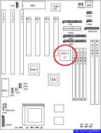
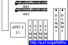
| QuickLinks | Home | GA-586HX | Hot-Swap | AP5T-3 | Q3Test/TNT2 | PA-2012 | H/W-Hack | JiuZhaiGou | Wallpaper |
This page now includes How? info for the both the AP5T-3 (Revision 3.1) and AP5T-2 (Revision 2.0) mobos. The AP5T-2 portions, in green, were generously contributed by Nimrod via email and published here in verbatim. This is what I call an "Internet" collaboration and It is refreshing! This is the true spirit of the Internet.
I jumped onto the Web and did a lot of browsing. I used Deja.com to search the alt.comp.periphs.mainboard.aopen and alt.comp.periphs.mainboard forums. I then grabbed a multimeter and began an intense study of the mobo itself, tracing leads and jumpers, and measuring resistors. I also surfed to the AOpen tech Support Page and downloaded everything related to the AP5T.
BIOS : ap5t180exe.zip (119KB, Easy Flash file) or ap5t180bin.zip (109KB, BIN file)
BIOS Flasher - Required for BIOS in BIN file : af535a.zip
User Manual : ap5t-3man.zip (412KB, PDF file)
AOChip Utility - Removes "?" in Win95
Device Manager : aochp103.zip (22.3KB)
Jumper Settings : Jumper Table Summary of AP5T-3
AP5T-2 Jumper
Settings : http://www.aopenusa.com/tech/jumper/ap5t-2/default.htm
AP5T-x Jumper
Settings : http://www.weblink.com.tw/wiiservice/qa2-1.htm
Board Benchmark
: http://sysdoc.pair.com/aopenap5t.html
The are 3 major revisions of the AP5T; revisions 1, 2 and 3. There are also many minor revisions like 3.1, 3.4, etc. Mine is the AP5T 96152-3.1 or Revision 3.1.


[AP5T-2]
My revision is 96152-2. This should be
the major revision 2 board.
The latest version of AP5T BIOS released by AOpen is version 1.80. Look here for more info on this version : AP5T BIOS v1.80.
AOpen's BIOS come in their Easy Flash format, which is a combo of the BIOS file and the BIOS flasher. The BIOS can be flashed simply by running the file since it is an EXE file. Alternatively, the BIN format is available on my webpage above and can be used together with the AF535A.EXE flasher.
I flashed the BIOS using this procedure :-
This is what the CTBIOS utility reports :-

[AP5T-2]
There is nothing to add. I also downloaded and installed
this version of the BIOS. The BIOS doesn’t do anything,
besides prompting AMD K6-3. It doesn’t turn on the Write
Allocation. L
Perhaps older versions will run ???
4. Set the clock multiplier and bus frequency
The clock multiplier is controlled by jumpers JP3, JP1 and JP2. The bus frequency is controlled by jumpers JP6, JP4 and JP5.
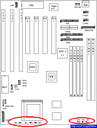


This table shows the clock multiplier settings :-
| K6-2/K6-III Clock Multiplier |
BF2 | BF0 | BF1 | JP3 | JP1 | JP2 |
| 2.5 | 1 | 0 | 0 | 1-2 | 2-3 | 2-3 |
| 3.0 | 1 | 1 | 0 | 1-2 | 1-2 | 2-3 |
| 3.5 | 1 | 1 | 1 | 1-2 | 1-2 | 1-2 |
| 4.0 | 0 | 0 | 1 | 2-3 | 2-3 | 1-2 |
| 4.5 | 0 | 0 | 0 | 2-3 | 2-3 | 2-3 |
| 5.0 | 0 | 1 | 0 | 2-3 | 1-2 | 2-3 |
| 5.5 | 0 | 1 | 1 | 2-3 | 1-2 | 1-2 |
| 2.0/6.0 | 1 | 0 | 1 | 1-2 | 2-3 | 1-2 |
This table shows the bus frequency settings :-
| Bus Frequency | JP6 | JP4 | JP5 |
| 60MHz | 1-2 | 1-2 | 2-3 |
| 66MHz | 1-2 | 2-3 | 1-2 |
| 75MHz | 2-3 | 1-2 | 2-3 |
| 83.3MHz | 2-3 | 2-3 | 1-2 |
These are the settings I tried :-
| CPU Frequency | Clock Multiplier | Bus Frequency | JP3 | JP1 | JP2 | JP6 | JP4 | JP5 |
| 366MHz | 5.5 | 66MHz | 2-3 | 1-2 | 1-2 | 1-2 | 2-3 | 1-2 |
| 375MHz | 5.0 | 75MHz | 2-3 | 1-2 | 2-3 | 2-3 | 1-2 | 2-3 |
| 400MHz | 6.0 | 66MHz | 1-2 | 2-3 | 1-2 | 1-2 | 2-3 | 1-2 |
| 412.5MHz | 5.5 | 75MHz | 2-3 | 1-2 | 1-2 | 2-3 | 1-2 | 2-3 |
[AP5T-2]
The AP5T-2 doesn’t have any jumper for the BF2. The
clock multiplier is controlled by jumpers JP1 and JP2.
The bus frequency is controlled by jumpers JP5, JP3 and
JP4 (which have the same meaning as JP6, JP4, JP5 for the AP5T-3).
If you want to have a multiplier like 4.0, 4.5, 5.0 or 5.5 for
the AP5T-2 you have to hardwire the BF2 jumper on the CPU socket
directly. This is not so dangerous as it sounds. Simply remove
the CPU from the socket, take a very small iron cable (0.1mm or
smaller) and put it in the pins of the CPU socket as depicted in
the figure below. Then reinsert the CPU.

I have selected a bus frequency of 75 Mhz and a multiplier of 5.0 (i.e. 375 Mhz). 5.5 would also work, but the CPU gets very hot then, so you would perhaps need an extra cooler.
If you don’t want to do this tweak, you can select a multiplier of 2.0 which results in 6.0. This works without modifying the BF2 pins.
The AP5T-3 has a bank of jumpers called JP11 that controls the amount of core voltage supplied to the CPU. It consists of 6 sets of 2-pin jumpers.
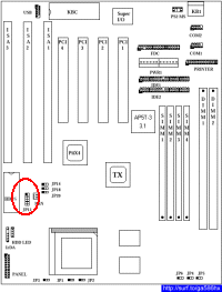
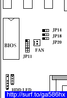
This table shows the different core voltage settings :-
| JP11 | Core Voltage |
| 1-2 | 3.45V |
| 3-4 | 3.52V |
| 5-6 | 2.9V |
| 7-8 | 2.8V |
| 9-10 | 3.2V |
| 11-12 | 2.5/2.2/2.0V |
At first glance, JP11(11-12) looked promising, but it was a let down. According to the user manual, the jumper position is reserved and the voltage is most likely 2.0V. To be sure, I measured it.
Measurement of the core voltage required 4 things; 3 100W resistors and 1 multimeter. I jumpered JP11(11-12), removed the CPU, inserted the 3 resistors as shown in the diagram below, and locked the socket lever. I removed all cards and RAM from the mobo, and connected the power supply. After switching it on, I measured the voltage across the 100W core voltage resistor with the multimeter. These is the sad result :-
Core Voltage = 2.0v

[AP5T-2]
The AP5T-2 has also a bank of jumpers, called JP7
that controls the amount of core voltage supplied to the
CPU. It consists of 6 sets of 2-pin jumpers.
| JP7 1-2 3-4 5-6 7-8 9-10 11-12 |
CPU Core Voltage (Vcore) 3.45V (P54C or IDT C6) 3.52V (Cyrix or AMD K5) 2.9V (AMD K6-166/200 & Cyrix M2) 2.8V (PP/MT P55C) 2.7V 2.5V |
Measurement of the core voltage was the same as for the AP5T-3. (I didn’t remove any card or RAM and everything worked fine afterwards J . But it’s for sure safer to remove everything.)
I measured the core voltage with the multimeter. And the 11-12 pins have really 2.5 V.
Evidently getting the required core voltages was going to take more work. Armed with the multimeter, I began a detailed study of JP11 and the area around it. This is what I found.
JP11 consists of 6 pairs of jumper pins and there are 7 surface mounted resistors on its right side. The jumper pins and resistor are connected as shown in this diagram.

I was only interested in the last 4 jumpers and resistors because they correspond to dual or split voltages. Using the multimeter, I measured the resistance of each resistor and the actual core voltages with JP11 jumpered. These are the results :-
| JP11 | Resistor | Actual Core Voltage(V) | Resistance(KW) |
| 5-6 | R2.9 | 2.92 | 20.00 |
| 7-8 | R2.8 | 2.79 | 21.58 |
| 9-10 | R3.2 | 3.25 | 16.85 |
| 11-12 | R2.0 | 2.00 | 43.13 |
From these readings, it can be seen that as resistance increases the core voltage decreases non-linearly. So to obtain the desired 2.2v and 2.4v, I had to add resistance. After some(a lot of) trial and error, I came up with these results :-
| JP11 | Resistor | Resistance (KW) |
Added Resistance(KW) |
Total Resistance(KW) |
New Core Voltage(V) |
| 5-6 | R2.9 | 20.00 | 14.90 | 34.90 | 2.18 |
| 5-6 | R2.9 | 20.00 | 13.60 | 33.60 | 2.23 |
| 5-6 | R2.9 | 20.00 | 9.90 | 29.90 | 2.35 |
| 7-8 | R2.8 | 21.58 | 6.70 | 28.28 | 2.42 |
| 5-6 | R2.9 | 20.00 | 6.70 | 26.70 | 2.49 |
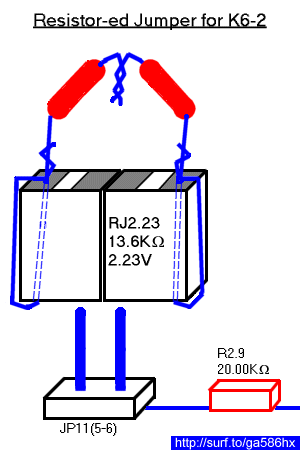
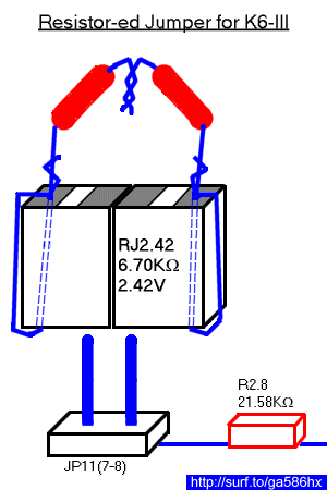
To add resistance, I created what I call Resistor-ed Jumpers (RJ). Each RJ is made up of 2 jumpers and 1 or more resistors. I made 2 RJs; one for the K6-2 and one for the K6-III.
For the K6-2, I used a RJ
with resistance of 13.60KW and
added it to JP11(5-6). This gave a total
resistance of 33.60KW and a core voltage of 2.23V.
For the K6-III, I used a RJ with resistance of 6.70KW and added it to JP11(7-8). This gave a total resistance of 28.28KW and a core voltage of 2.42V.
Important Note :
Newer versions of the
K6-III use a 2.2V core voltage instead of 2.4V. See the K6-III
Core Voltage page for more
info.
[AP5T-2]
The rework for the AP5T-2 was very similar. I decided to
work only with the 11-12 pins.
For the K6-2 we need 2.2V. A 8.5 KW resistor between 11-12 will do what we need. The processor has a tolerance of 0,1 V, so if you donnot have this resistor at hand, I think all resistors between 8 KW and 9.5 KW will do it. A 9.5 KW resistor results at 2.1 V.
For the K6-3 we need 2.4V (with also 0.1V tolerance). A 3 KW resistor between 11-12 will produce 2.4V. I use a 3.6 KW resistor (2.36V) in order to reduce the power consumption. I think that all resistors between 1 KW (2.46V) and 4 KW will fit well.
One warning!!!
In a newsgroup article I read, that someone suggested to treat
the AP5T voltage jumper the same like the voltage jumper for the
ASUS T2P4. The T2P4 voltage regulator can be controlled by
closing more pins on the jumper bank (e.g 1-2 and 9-10). By doing
this, the voltage is getting less. I tried it out with the AP5T
(closing 1-2 and 9-10) and this resulted at 4.82 V, so here, the
voltage gets more by closing more pins. At high voltage
processors can get severe damage, so donnot do this.
One antiwarning ;)
If you donnot close any pins, the voltage is only 1.23V. At this
voltage the processors donnot run, but on the other hand, they
donnot get any damage. So if you plug in a resistor and the
contacts to the pins do not work the processor does not get any
harm, because we have only 1.23 V.
7. Cross 'em toes and boot 'er up!
Upon bootup, the BIOS detected the K6-2 as a K6-2 375MHz. For the K6-III, it hanged at exactly the same place as with my GA-586HX mobo. After I entered the BIOS setup and set System BIOS Cacheable=DISABLED, it booted without problems and detected the CPU as a K6-3 411MHz. I booted to DOS and Windows 95 OSR2 (AMDK6UPD patched) with no problems.
I tried the SETK6V2 (setk6v2.zip (157.0KB) or Website) to see whether the BIOS enables Write
Allocation. It did not.
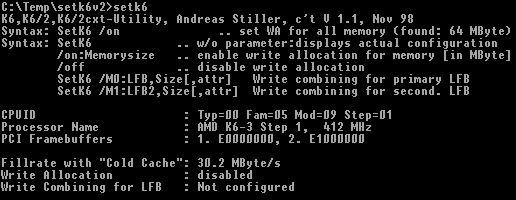
However, Write Allocation can still be
enabled by running the SETK6V2 utility.

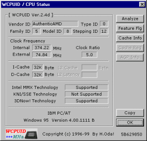
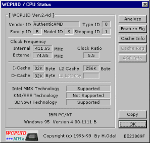
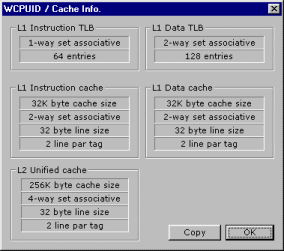
These are what WCPUID utility (wcpuid.zip (57.6KB) or Website) reported :-
K6-2 375MHz (75 x 5.0)
K6-III 411MHz (75 x 5.5)
To test the entire system stability, I ran Winstone 98 in "demo" mode. This mode runs through the benchmark, reboots and then starts all over again. I ran it this way for more than 6 hours.
It worked fine!! :)
[AP5T-2]
For the AP5T-2 you also have to disable SYSTEM BIOS
Cacheable. Perhaps the BIOS Code has a bug with fast processors.
Win95 has also problems with processors faster than 350 Mhz. It
does not boot and produce an internal IO error. The tool AMDK6UPD
will fix this bug. You have to boot Win95 at a lower speed than
350 Mhz in order to apply this bugfix.
In order to keep the processor cool it is highly recommended to install a CPU cooling tool for Win95 (Win NT, OS/2 and Linux already have these tools within the kernel).
There is also a newer tool SETK6V3 but it sometimes crashed on my system, so I use SETK6V2 now.
To measure the memory performance of the AP5T-2 I benched the board with the tool ctcm16l.
With write allocation
turned off, the overall performance was:
136.8 MByte/s with 256 KB L2-Cache /DOS (640K)
72.2 MByte/s with 256 KB L2-Cache /Win (4M )
with write allocation
turned on, the overall performance was:
281.1 MByte/s with 256 KB L2-Cache /DOS (640K)
148.0 MByte/s with 256 KB L2-Cache /Win (4M )
So turn it on J
| QuickLinks | Home | GA-586HX | Hot-Swap | AP5T-3 | Q3Test/TNT2 | PA-2012 | H/W-Hack | JiuZhaiGou | Wallpaper |