

If you want, you can go straight to the "how-to" part.
A speaker is a complex device intended to transform electric power into acoustic power. That means, we feed it with voltage and current and it displaces air, giving us sound pressure and volumetric velocity over a given acoustic impedance (the cabinet where the speaker is mounted and the room you're playing). In a black box approach, it could be represented as follows:
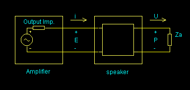
This "model" can be subdivided into two smaller parts if we think of how speakers work. First, the electric power is transformed into mechanical power (movement of the cone - we apply a force to the cone and it moves with some velocity) and then this translates into sound (a certain volume of air is displaced creating sound pressure).
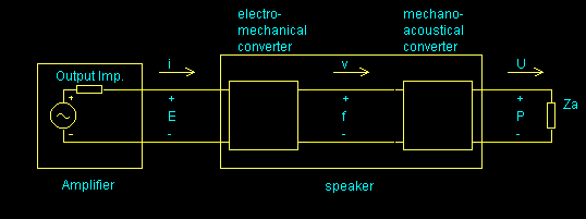
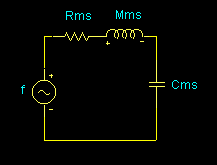
Let's have a look inside each of the above "black boxes" (we call it quadripoles in engineering). First thing we need is a way to represent mechanical and acoustic quantities in a suitable way for us with background in electronics to understand and analyze. The force applied to the cone is equal to its mass times acceleration, according to Newton's law. Acceleration is the derivative of velocity. The suspension works like a spring, where force is proportional to displacement. Velocity is the derivative of displacement. Some energy will be lost in the form of heat. If we wrote the differential equations for this system, we would end with something exactly like a RLC electric circuit, with the mass corresponding to the inductance, the compliance of the suspension corresponding to the capacitance, the losses represented by a resistance, velocity equivalent to current and force equivalent to voltage. We can model our mechanical system with an equivalent electrical circuit, where Mms is the inductance equivalent to mass (the little m stands for 'mechanical', the s for 'speaker'), Cms is a capacitance that represents the compliance of the suspension, Rms is a resistance that represents the mechanical losses, f is a voltage source equivalent to the force applied to the cone, and v is the current equivalent to the velocity of the cone.
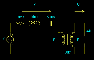
In a similar way, the acoustic quantities sound pressure P and volumetric velocity U are analog to voltage and current, respectively, and the relation between them is given by an "acoustic impedance" Za. If the speaker is mounted in an open back cabinet, Za can be considered a short circuit compared to the other impedances in the model, but if it is mounted in a closed back cabinet Za behaves like a capacitance Cab (the little a stands for 'acoustical' and the b for 'box' - the cabinet). Any losses by absorption, leakage through the cabinet walls and by the cabinet not being 'solid' enough are represented by a resistance Rab. In closed and open back cabinets we can normally ignore it. Almost no guitar cabinets are of the bass-reflex type but the port would be modeled by an inductance Lab.
Pressure P is equal to force f divided by the effective area of the cone Sd. Volumetric velocity U is equal to the velocity of the cone times this area. If P and f are "like" voltages and v and U are "like" currents, then the relationship between them is like we had a transformer with transform ratio Sd:1.
The force applied to the cone is equal to the current flowing through the coil times the flux density B times the effective length of the coil L. If we move the cone, a potential will appear at the speaker terminal that is proportional to the velocity of the cone (back emf). If we think of force as "voltage-like" and velocity as "current-like", then we can't model their relationship with voltage and current at the speaker terminals by a transformer, but with a gyrator with gyration constant BL.
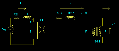
Re and Le are the DC resistance and the inductance of the coil (guess it - 'e' is electrical), not considering the effects of the mechanical and acoustic components. If we now reflect the impedances from the acoustic and mechanical sides to the electrical side, we can find the impedance "seen" by the amplifier:
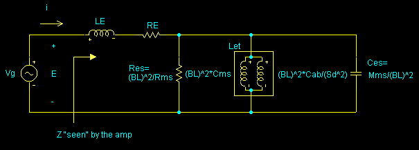
Where Res=(BL)2/Rms, Let=(BL)2*Cmt, Ces=Mms/(BL)2 are the result of 'reflecting' the impedances of the acoustical and mechanical sides to the electrical side. If we are using a closed cabinet, Cmt (t is for 'total') is the series association ('mathematical parallel') of Cms and Cab/Sd2 (Cab reflect to the mechanical side). If it's an open back cabinet, Cmt=Cms.
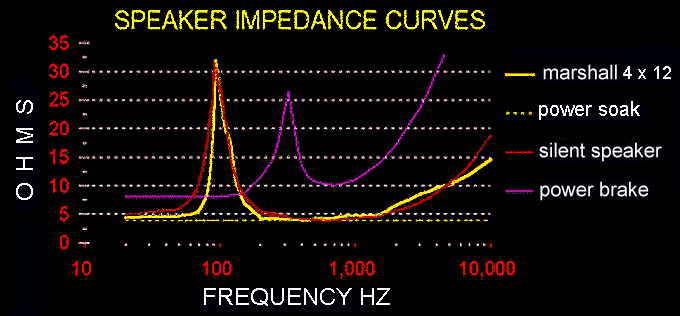
If we plot the impedance "seen" by the amplifier against frequency, it would look like these pictures (power brake, power soak, and silent speaker are trademarks of Marshall, Scholz and Kolbe respectively):

We can measure the values of Re, Le, Res, Let and Ces for any speaker using a signal generator, a large value resistor and a multimeter, and use it to build a reactive load that will "look" to your amp just like the speaker it is used to. This is not a speaker emulator, since we are only emulating how the speaker loads the amp, not how it translates electricity into sound. You can attenuate the signal at the reactive load's terminals and feed it to a guitar speaker or another lower (or higher) wattage guitar amp, but if you feed it directly to a mixing board, tape recorder or headphones it will not sound like your speaker. You will need to do some filtering (one second order high pass filter for closed cabinets, an additional first order high pass filter for open back cabinets, a very steep low pass filter and some notches and peaks). Take a look at LHX2's home page for some nice simulators you can use together with this load.
Re is the resistance of the speaker as measured with a multimeter. This is the setup for measuring the other parameters (speaker must be mounted in its cabinet) :
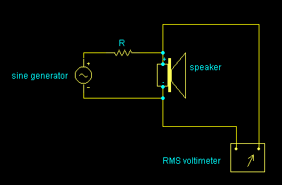
Since R is much greater than the impedance of the speaker at any frequency, current through the speaker will be constant (for practical purposes). If the generator is set to 3.3 V and R is 3.3k, this is equal to 1 mA. So each mV at the speaker terminal will be equivalent to 1 ohm. We need to find the frequency at which the impedance is maximum. Call this frequency f0 and this maximum impedance Z0. We can now find Res=Z0-Re. We now find the two frequencies fa (above f0) and fb (below f0) where the impedance falls to Re+Z0*0.7. The difference between them will be called BW. Now
Last we find the point where impedance is twice the value of Re. Call this frequency fx.
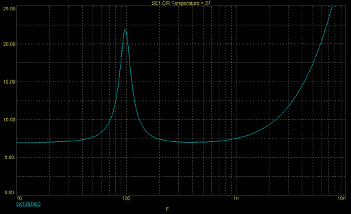
For a classic Celestion loudspeaker f0 is approximately 95 Hz, fx is around 3.9 kHz, and the values would be something like this (rounded to standard values):
With these values the impedance would be this:
The capacitor should be of an adequate
voltage and current rating, and non-polarized. The resistors
should be of high wattage. Inductors must use large wire and have
air core (or big iron cores of very good quality). Provision
should be made for the heat to be dissipated. In other words, the
more power your amp is going to deliver, the bigger the reactive
load will have to be. And the thing will get HOT,
so you better take care when touching it. The inductors can be
wired by people who make passive crossovers for loudspeaker
boxes.
There's a post from Randall Aiken in Duncan Amps page, where he describes a reactive load. His approach is a little different from mine, but in the end the results are similar. Randall's post is interesting for the DIY'er because he includes power and voltage ratings for all components, which I don't.
This page hosted by ![]() Get your own Free
Homepage
Get your own Free
Homepage