

Adams motor. Experimental results, circuit diagrams and AVR Basic programs
Author: Sergey Stanislavovich Abramov, Cand.Sc., Saint Petersburg, Russia
Introduction
Adams motor [1-3] is considered a free energy device. It relates to electric machines called Switched Reluctance Motors (SRM) [4]. Some aspects of the theory of operation related to the Adams motor- generator are available on this web page. You can also visit the home page by Robert Adams with links to his articles and books. I don't mean to claim that my replication of the Adams motor has been extremely successful, but I designed several control circuits and evaluated technological problems of this design. I carried out some experiments with my AVR controller based circuit. It should be noted that free energy research is not my main occupation, of course.
My experimental results and some conclusions were presented in the New Energy Technologies magazine [6], published by its editor-in-chief Alexander Frolov. A theory related to the Adams motor running was briefly expounded in my article . I considered this review useful for those Russian readers who had never heard of this machine. This magazine has an English version too and is available on the Internet, but the password is required to enter it.
I have found several notes that all processes in an Adams motor can be described on a basis of the existing electromagnetic theory. Still if any free energy source existed it would be vainly to explain overunity effect as an electromagnetic phenomenon in the Adams motor in itself.
Michael Barrie Smith living in Australia wrote he had managed to obtain overunity in a system including an Adams motor and two batteries. He considered that his battery oscillated at its resonant frequency making energy flow from zero point fluctuations into the battery. At present his web site doesn't exist. To better understand physical phenomena in these devices it is necessary to take into account the chemical features of accumulators. This signifies that the charging effect very likely depends on the motor frequency. So the motor (SRM) with adjustable speed could be suitable to verify this hypothesis. As far as I know Lutec (Aust.) Pty Ltd are ready to sell their 1 kW, 1500% efficiency generator throughout Australia, and this device includes a variation of the Adams motor - generator with mechanical commutation of the stator current, as per Tim Harwood. I have assembled a control circuit of my own which can charge the second battery but the results don't seem as great as those obtained by Michael. The description of my last experiment with a two-battery set-up is at the end of this web page.
I think the zero point concept [8] can be regarded as a truthful basis for the processes in a system including Adams motors and accumulators. To better understand the free energy phenomena and find useful information about the so-called " Gray motor" read the book [9] by A.Lindemann. There I have found an interesting note that the device should be regarded as a secondary one, while the genuine free energy process takes place outside it. Some researchers consider energy gain takes place when the electromagnetic field vanishes. It would have been impossible if vacuum had been absolutely empty. Zero point theory regards vacuum as active medium capable of producing virtual particles. So if any device can extract this vacuum energy no law of physics is violated.
My report is written "as is". I have not arrived at a definite conclusion as to the feasibility of free energy extraction. In 2002 two interesting projects, namely POD (Power On Demand) and ACG (Air Core Generator) started in the Adamsmotor e-group. The main idea was to eliminate moving parts as the Adams motor design requires a very well balanced and light rotor, low friction bearings. Originally the efficiency factor of 2.0 was announced. A lot of tests were executed by Jean Michel Cour on the basis of his own circuits. His opinion of overunity characteristics of these devices is negative. Still unsuccessful replications don't imply the entire failure of the projects. I have read a lot of messages in some Yahoo groups from people who readily joined the free energy research but later rejected its possibility due to their own reverse.
In 2001 I was looking through some web sites containing references to John Bedini's variation of the Adams motor. To form a notion of his devices visit Bedini's web page. Still it seems to me that some of them don't resemble the Adams machine. Besides I found references to a design known as "school girl motor". Its idea is also ascribed to Mr Bedini and this machine is more similar to the Adams one. At first I thought that overunity characteristics had already been reached in this motor. I didn't try to replicate it as it was reported not to be a self-starting machine and several its features didn't seem clear for me. But others replicated this device and there took place some conclusions about the absence of any remarcable features.
My own experimental results
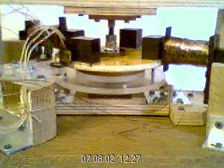
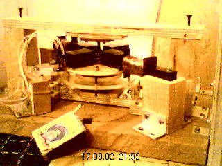
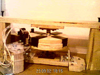
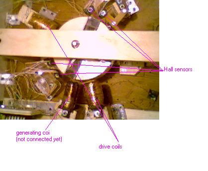
I've been experimenting since April, 2002. To get a relatively good result I rebuilt several rotors. This is normal, so did many experimenters. My first motor's design only allowed the rotor to rotate at the speed of 800 rpm at 12 Volt. The ball bearings weren't fixed good enough and their axes needed to be aligned thoroughly to eliminate vibration. So I changed to another design which is represented by the photos. The movable base allowed me to better align the axes of the bearings. That made it possible for me to increase the speed to the range of 1700 to 1800 rpm, when only one stator coil worked. It is well-known that in Adams motor the current impulse should start when the magnet passed several degrees by the coil centre. But my rotor rotates much faster if the triggering point is set slightly before this centre. I think this phenomenon is caused by the total inductance of my circuit. Most likely if optical switching was used it would be possible to establish the triggering points past the drive coils. My control circuit containing an optical switch is already capable of working but it needs arrangement or any better switch.
|
|
|
I tried to extremely reduce the air gap taking into account the safety of the motor. I couldn't measure it exactly but estimated its value as 1 mm at the edges of a magnet. Of course in the middle of it the gap is larger, as all my magnets have flat sides. With such an air gap the transistor became slightly warm and the speed reduced to 1450 rpm instead of the previous value of 1750 rpm. Hence it is not worth making the air gap less than 1 mm. At first looking through the web sites dedicated to Adams motor I found instructions kind of "the air gap isn't critical but the closer the better". Later Tim Harwood noted that the air gap shouldn't exceed 1-1.2 mm not to make the motor characteristics worse. Maybe I was the first experimenter to point out there should be the least suitable air gap. Very likely it was a known fact but it had not been expressed on anybody's web site directly. If you are familiar with the electric machine theory it is obvious for you that every machine has its proper air gap. Usually it is larger in synchronous machines than in induction type motors. So it isn't strange that Adams motor has its own air gap range. At present you can find similar notes on other web sites. I don't know if it is a confirmation of my results or direct use of them without any reference. This also relates to my notes about the triggering points of the stator current (see above). In any case it is not easy to measure very short air gaps without a special instrument and ensure the safety of the motor.
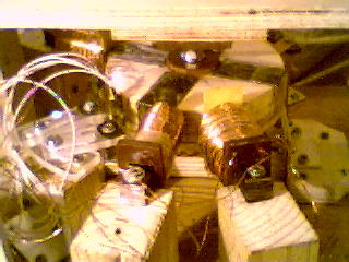
As to my motor design three small discs were placed between two large ones. This design permitted me to reach relatively good balance. But the magnets seemed like cogs. So the aerodynamic losses were palpable as the rotor acted like a fan. Therefore I made two veneer details and fixed them on the rotor to obtain a smooth shape. Of course the CD rotor is not so heavy as mine. Originally I wanted to make a sectional design. At present I can remove the upper bar, then the lower and upper nuts and washers which keep the discs on a shaft and then separate a disc with magnets and veneer details. Still it is sensible to avoid ball bearings in the toy-sized Adams motors. I have done my best to eliminate vibration and succeeded in this work, to a certain extent. But the vibration remains palpable. Very likely Tim Harwood's design seems better in reference to low voltage, low power motors. As to my stator's winding it should be noted that the wire (0.45 mm) is wound around a laminated core. To get iron strips I disassembled an old radio transformer. The core has the dimensions of 10x11x50 mm.
Having put into my device a new battery with the capacity of 1,3 Ah, I reached the speed of 2600 rpm at 12.2 Volt. My previous batteries (9 V, 0.125 Ah + 3x1.2 V, 1.5 Ah) were only suitable for a radio set. Maybe that was due to their high internal resistance.
|
|
|
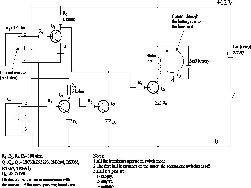
My 4 ferrite magnets have the dimensions of 20x20X35 mm and are fixed on a disc having the diameter of 105 mm. Hence I couldn't get sufficiently short impulses. Therefore I established two hall sensors to switch the current in a coil. At first I tried to control my motor by the original Tim Harwood's circuit containing 1 transistor and 1 hall sensor. But my experiments demonstrated that without a diode and a 100 ohm resistor in the base circuit of the transistor it was impossible for me to get a suitable switch mode. My circuit does work but still it would be preferable to adjust a duty cycle at starting of a motor. In this transistor design it remains constant. Later I corrected this deficiency in my controller based circuit.
There took place claims that Adams motor can rotate without discharging of a 4 Ah battery. But so far I haven't been able to reach this regime. So I've been experimenting with two- battery setup. I heard of the idea of using very large capacitors (approximately 50000 microfarad or higher) to stop the physical flow of electrons between poles of a battery while driving a load. A battery takes time to deliver energy whereas a capacitor can deliver it much faster, this gives faster rise times. When I used a 100 microfarad capacitor there wasn't any noticeable effect. It's important to note that the capacity should be from 0,05 to 1,0 Farad, as per Michael Smith.
In my first two-battery design without a timing circuit the voltage of the 2-nd battery increased but later I came at a conclusion that voltage rise was due to a known battery property. The battery voltage can increase if it is subjected to voltage spikes but it doesn't mean the charge actually grows. During one of my experiments after 75 minutes running the drive battery lost 0,17 Volt whereas the increase of the voltage of the charging one was 0.36 Volt. The capacity of both batteries was equal in that experiment. It should be taken into account that the voltage always falls after charging. In my subsequent experiments other values were obtained, depending on the accumulator discharge. To evaluate the charge gained by the second battery the density of electrolyte can be measured, if you have non-hermetic battery. Still it is easier to measure the voltage not long after the motor stop.
In my first two-battery design without a timing circuit the voltage of the 2-nd battery increased but later I came at a conclusion that voltage rise was due to a known battery property. The battery voltage can increase if it is subjected to voltage spikes but it doesn't mean the charge actually grows. During one of my experiments after 75 minutes running the drive battery lost 0,17 Volt whereas the increase of the voltage of the charging one was 0.36 Volt. The capacity of both batteries was equal in that experiment. In my subsequent experiments other values were obtained, depending on the accumulator discharge. To evaluate the charge gained by the second battery the density of electrolyte can be measured, if you have non-hermetic battery. Still it is easier to measure the voltage not long after the motor stop.
To obtain a relatively uniform torque I added the second stator controlled independently. In my last motor the stators are established so that the angle between their axes equals 135 (180- 90/2= 135) degrees. Therefore my motor began rotating at the speed of 3300 rpm at 12 Volt. The power consumption increased though. But I think it is not worth obtaining extremely high speed, if this is reached at the expense of higher stator current. It should be mentioned I felt electric shock due to high voltage spikes when the motor was rotating at this speed and I touched one of the coils. My digital ammeter was displaying about 120 to 130 Volt.
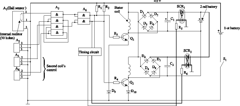
I've designed and tested a control circuit including 2 digital microcircuits, 4 hall sensors and 2 power transistors. The timing circuit determines the triggering points for discharge of the capacitors C1 and C2. They charge during the current commutation in stator coils through the bridge rectifiers D1-D4 and D6-D9. This charging circuit is more efficient than my first one where the second battery was charged directly through a diode. It is more convenient to store the energy in capacitors than directly charge the battery by the stator current. In the latter case heat losses must be higher.
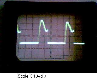
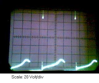
Below you can see the current impulses and spikes of the coil voltage in one of my coils. I suppose the fronts of impulses should be shorter. The impulses have unequal amplitudes due to the difference in magnet characteristics. Most likely the air gaps are slightly different despite the fact that I have done my best to make them equal. The voltage spikes reached the value of 140 Volt and the speed was about 1600-1700 rpm in that experiment.
|
|
|
|
Temperature measurements
To estimate the temperature of coils I used manual control, a thermocouple and coil resistance measurement. If the temperature rises so do the resistance of copper wires. My coil resistance equals 5 Ohm. During one of my experiments temperature and coil resistance were measured before the motor's start. After half an hour running I made the motor stop and executed measurement once again. The temperature probe showed 1 degree of overheating and the digital ohmmeter's reading was the same 5.0 Ohm. I cannot agree with Tim Harwood in respect to his notes about the cooling effects in working motors. If his motor runs at the temperature below ambient this phenomenon takes place, of course. But the cooling effect can't be mentioned if the motor is slightly warm like mine. Look at my current impulses, their amplitude doesn't exceed 0.35 A. The equivalent effective direct current is around 0.15 A. So the power losses in a stator are equal to I^^2*R=0.15^^2*5= 0.1 Watt!. If's obvious impossible for the stator to get hot due to these naught losses! There is a rough analogy between DC or AC machines rotating in the idle mode and the unloaded Adams motor. This is a formula for a current in a DC motor running in a steady state: I=(U-E)/R=(U-CFn)/R. The variable U denotes the applied voltage, E is back emf which is proportional to the electromechanical coefficient C, magnetic flux F and speed n, R is an armature resistance. Due to the back emf influence the current is fairly low in the idle mode what is similar to rotating Adams motor characteristics. Hence there are no reasons for overheating. Without this back emf the current would be very high. It is just the same as what immediately happens when the machine is connected to a voltage source. The current in a starting induction machine is 6 to 7 times greater than that in a steady state under load. Isn't it similar to the current draw in a starting Adams motor which subsequently halves? I think it is an ordinary phenomenon in all electric machines and doesn't require any cold current.
Important note: Adams motor is intentionally designed in a manner so as to remove the back emf out of the stator windings. Very likely this special feature if it really takes place doesn't allow us to directly apply the above mentioned analogy.
Some experimenters originally reported about their motors running below ambient temperature but later attributed this effect to a wind chill factor. One of the reports written by Todd Montgomerie is placed in the files section of the Just-Build e-group. Still this group was closed for the lack of any palpable results.
AVR controller based experiments
To reduce the amount of hall sensors a controller should be used. My control circuit comprises an AVR controller (AT90s2313-10PI). It only controls one stator but it's possible to modify the circuit to independantly operate several coils as well. Usually SRM type motors have 3 phases but this does not seem necessary in reference to Adams motors in free energy experiments.
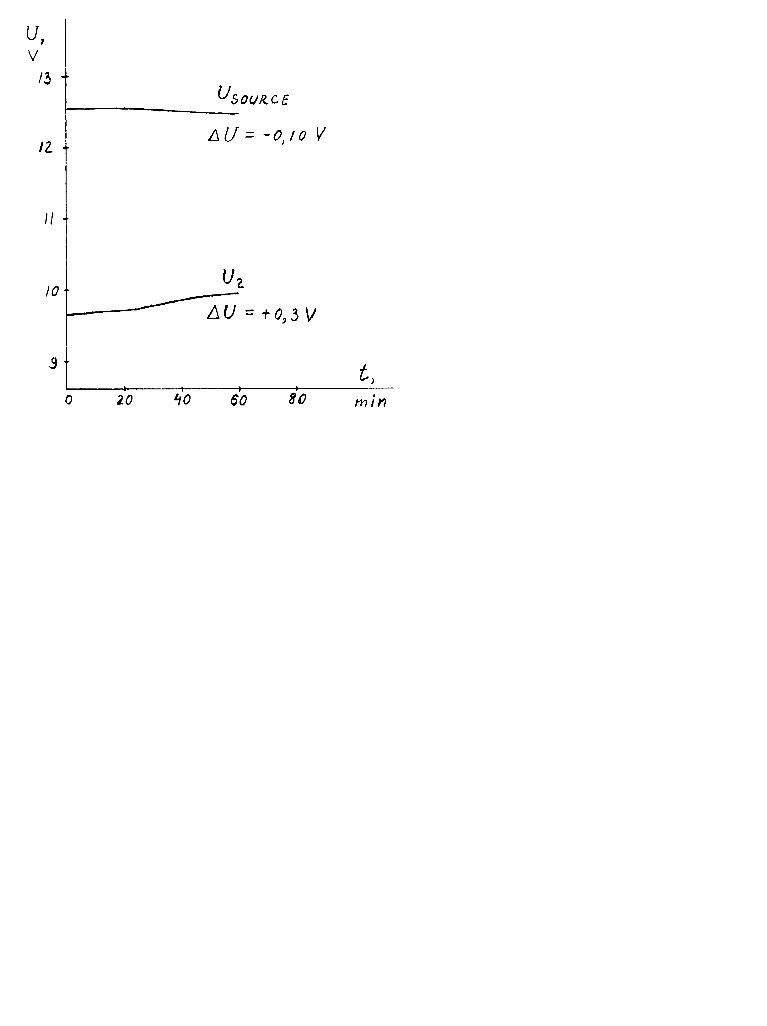
My simple Basic program ensures starting of the motor and generates short impulses on PB3-pin to turn on the opto-thyristor which makes the capacitor charge Battery 2. The experimental results are in this diagram. The source and the second batteries had the capacity of 1.3 and 5.0 Ah respectively, hence the latter was almost 4 times as large. In M.B.Smith's set-up these parameters were 4 and 60 Ah. As per Mr Smith if the capacity of the second battery is insufficient it can't absorb the excess energy provided that the latter actually takes place. I think this capacity depends on the motor power range and can be considered the critical parameter of the device. At first I thought that just the battery capacity ratio determined the efficiency of the device in question, but now I regard this hypothesis as wrong.
Originally the voltages of my unloaded source and charging batteries were 12.91 and 9.56 Volt. When I started the motor these voltages immediately changed to 12.55 and 9.63 Volt. After an hour running the source battery lost 0.10 Volt (12.55 - 12.45 = 0.10 Volt under load), another one gained 0.30 Volt (9.63 + 0.30 = 9.93 Volt). The next day their voltages were 12.74 (-0.17 Volt) and 9.64 Volt (+0.08 Volt). To my mind these figures don't enable me to estimate the actual change of the charge of both batteries. Michael's results reported were much better. Still several years ago he wrote me he had failed to repeat the result! Later I found a comment about the Adams motor that pointed out the battery ability to recover after being subjected to high voltage spike influence. If the battery has not worked for a long time it runs out of order but these spikes can partially recover it. Maybe Michael faced this effect and attributed it to energy gain. As to the temperature of my device the power transistor overheating resulted in 3 degrees, the coil got 2 degrees over ambient temperature. To my mind if even Michael's successful experimental result actually took place it is rather difficult to properly adjust a motor and a control circuit to reach overunity. I think I know how to improve my design (e.g. optical switching, additional stator turns, etc.) but the possible energy gain isn't guaranteed, of course. By the way I wasted my week's spare time trying to make the circuit with a PNP-transistor work as Tim Harwood had described. I can't understand how has he succeeded in his very simple circuit. Besides I have never seen the scope readings of his stator current. To my mind it doesn't matter what transistor is used if the circuit is able to make backward current flow into the battery. Tim reported he used a mosfet in his later circuits.
My stator current impulses had rather sloping fronts so the transistor got hot. So I was forced to return back to my circuit with an NPN-transistor with the diode D4 connected to its emitter (see my transistor circuit). It should be noted that my motor is only controlled by the 1-st Hall sensor in the course of starting. This enables me to increase the driving torque. When starting process is over both sensors operate the stator current reducing pulse width and power consumption. Hence the flaw of my first transistor circuit is eliminated.
The version of Basic for AVR controllers (BASCOM_AVR) is available on the website DonTronics. The demo version of Bascom-AVR program is almost full-functional but is characterised by the restricted code capacity of 4K. That's enough to program my controller. Still only the commercial version enables compiling libraries. The comments in my program are blue-highlighted. As to the LED indicator it is used to adjust the triggering points of the stator current and is automatically switched off after starting.
If you decide to replicate my AVR based circuit it is essential to link your computer with a chip. It can be done via the LPT port as described on the Dontronics' web page. But if your matrix printer is already connected to this port it is desirable to use a PCI LPT controller or a device called In Circuit Programmer (ISP) which can be connected to a computer COM port. You can find the appropriate circuit on the website of the Silicon Chip company. I've already modified my circuit and a program so that it's possible for me to observe AVR controller variables on a computer display. The computer is connected to a controller via a Com port and a microcircuit Max232 as usual. Still the Windows Hyper Terminal has a fairly poor interface so any better program is required for this design. Visit the web site Windmill Software Ltd to download alternative free software.
There took place some claims about gravitational effects around a working motor. I found statements about the possibility of these phenomena looking trough the web pages dedicated to the Adams motor theory. Michael Smith also pointed out the possibility of these effects. To verify them it is likely possible to place a balance over the motor so that one mass is over the motor and the other is in a free space away from the motor. The mass above the motor should rise. As per Michael it is important to note the loads should be non-metal. Unfortunately my own experiment hasn't been successful. The balance wasn't affected by the working motor. Perhaps any better replication of the motor or more sensitive balance could detect the gravitational effect mentioned on some websites. To learn more about gravitational experiments you can visit the sites e.g. JL Naudin and Alexander Frolov. Jean-Louis Naudin also published his experimental results related to the Adams motor project. As to his "Lifter" experiments, Alexander Frolov expressed his rather sceptical attitude [7]. He considers these experiments are partially based on electric jet engine effect and are not related to Biefeld-Brown effect technology. According to A.Frolov significantly better results can be obtained with capacitors having a gradient of dielectric permeability. I also have read some more comments about Lifter's inefficiency in deep vacuum.
What's more I have read about the calorimeter test described on the web site http://www.aethmogen.com/. To my mind it seems to be a rather strange test and is unable to demonstrate any overunity effect. If anyone sets the device in question into an insulated box and the electric load he puts into another what conclusion must he arrive at observing the difference in heat amounts in these boxes? If I understood the author correctly the large amount of heat releasing in the second box should persuade everyone of the obvious overunity effect? Still in this case the energy source is a battery as usual and the Adams motor with its motor and generator windings acts similar to transformer. Lets put a transformer into the first box and repeat the experiment. Voila! Has overunity effect been proved by this calorimeter test? I doubt it though.
Notes
I am going to create another web site as free hosting by Geocities will come to its close later this year.
As I have spent a lot of time on another my web page having to do with power system simulation with the aid of Java and C++ software my free energy research is almost frozen at present. Still I hope to continue my experiments if it would be possible at all. Maybe if I find in the web any well documented device which is said to be a veritable overunyty one I'll try to create my own version. Recently I found some interesting links to pure permanent magnet motors which don't require any electrical or mechanical input at all.
Reference list
1 Patent No. GB 2,282,708 (from NEN,Vol. 4, No. 8, December 1996, pp. 1-7)
2 Nexus magazine, December-January 1993
3 Robert Adams, Applied Modern 20th Century Aether Science. Second Edition,2001
4 Miller, Switched Reluctance Motors and their Controls, ISBN: 10881855-02-03
5 Flux-machine and its analogues/ New Energy Technologies magazine, May-June, 2003, p.35-37
6 Sergey S. Abramov. Adams Motor/ New Energy Technologies magazine, May-June, 2003, p.15-20
7 New Energy Technologies magazine , March-April, 2003, p.73 (Russian version)
8 Puthoff H.E. Source of vacuum electromagnetic zero-point energy. Phys.Rev. A 40.4857-4862; also 44. 3385-3386
9 Lindemann A. The free energy secrets of cold electricity. Clear Tech. Inc. PO Box 37. Metaline Falls, WA 99153 (509) 446-2353
Caution:
The information presented is intended for non-commercial purposes only. If you use my information one way or another give a reference to my site, please. Any attempt to replicate the motor can be carried out at your full liability. These motors can develop high rpm and high voltage depending on how they are designed. Build and operate at you own risk. Free energy is still a matter of investigation but the magnet torn off the disc can be dangerous!
Last modified: 05/01/2009