|
A Frank Odell Web Page |
||||
 Page 5 |
||||
|
|
Page
Content
|
|||
|
A Frank Odell Web Page |
||||
Page 5 |
||||
|
|
Page
Content
|
|||
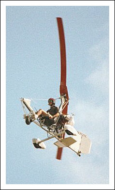
| Flight Systems of the Gyrocopter
System one, the engine: The engine-propeller
combination produces the thrust used to move the aircraft. The engine
produces rotational power and that power is transferred to the propeller
where it is If the engine fails to produce thrust the aircraft can not maintain altitude and airspeed. The pilot may point the nose of the aircraft towards the ground causing the aircraft to descend and can maintain airspeed by using gravity as a temporary energy producer. This is know as gliding flight and is a trade of altitude for airspeed. This maneuver will end when some object on the ground interferes with the flight of the aircraft. The gyrocopter can not glide as far as an airplane or glider, but will glide farther than a helicopter. System two, the rudder: The rudder is the
primary device System three, the rotor and blades: This
assembly is attached to the top of the vertical stanchion located behind
the pilot. In some two seat aircraft the
System four, ground handing equipment: The wheels, landing gear, is...
System five, instrumentation:
|
|
AUTOROTATION The motion of the rotor and the resulting lift depends entirely upon autorotation resulting from the air flowing up and through the slightly tilted rotor blades as the machine moves forward. Nature has applied the principle of autorotation for millions of years, seen in the whirling flight of the sycamore seed as it falls to the ground. Auto rotation slows its descent and the wind has greater opportunity to disperse the seeds over a wider area. The windmill was probably the first human invention which used autorotation, by harnessing the wind to produce rotary motion. The idea of a flying windmill, where rotating sails produced a wind to lift the machine, had a certain fascination with inventors, and among Leonardo da Vinci's thousands of drawings is an idea for flight along these lines. The real possibility for achieving such a machine was, however, delayed until development of the airfoil and the airplane which embodied this device. A windmill is basically an airscrew or propeller working in reverse, such that the air flowing over the sails is deflected by them, and exerts a force on the sails pushing them around. The sails effectively 'give way' to the wind and are pushed round by it. As early as the Middle Ages, however, it was realized that if the sails were set at a very flat angle to the wind they would be made to rotate against the airflow and thus be 'pulled' round into the wind. The principle here is the same as with a sailing ship which can 'tack' close to the wind, meaning it can move forward against the wind, at a shallow angle to it, if the sails are properly set. In much the same way a glider moves forward as it descends through the air. The rotor blades of an autogyro are shaped to achieve the same effect, and set at a shallow angle of about two degrees to the horizontal plane in which they rotate. The shape is that of an airfoil which enables the blades to turn into the airflow rather than be pushed round by it. When turning fast these rotor blades offer considerable resistance to the upward airflow, and it is their resistance that can be used to provide lift. The amount of lift created depends upon a compromise between the airspeed of the rotors, and the resistance the rotating blades offer to the airflow past them. In practice the desired lifting force is only produced when the blade speed greatly exceeds the forward speed of the machine. TAKEOFF To take off the rotor must produce adequate lift and it is necessary therefore to bring the rotor up to the required speed. This can be done in two ways. The first and simplest way is to propel the machine forward and, by tilting the rotor system back, making use of the airflow through the blades to build up the rotor speed. This, however, requires a suitably long runway. A second method involves more complex machinery but makes possible very short takeoff distances. Here the rotor is brought up to speed by a linkage to the engine used to provide the forward motion. When the rotor has the correct speed, the linkage is disengaged. The machine is then allowed to move forward and take off is achieved by tilting back the rotor system. Some autogyros can 'jump start' by over-speeding the rotor using the engine. The drive is then disengaged, and the rotor pitch increased. The aircraft jumps, using the stored energy, and continues then in autorotation. LANDING When the engine and propeller speed are reduced, the forward speed will decrease and the autogyro goes into a steady descent path. The autorotation principle still applies, as the air flowing up and through the rotor maintains the rotorspeed. A lifting force is therefore produced which, although insufficient to maintain the machine altitude, prevents it from falling like a stone. Even when the propeller is stopped, the autogyro will descend safely, under full control, from any altitude. In this respect the autogyro is at some advantage over the helicopter since in the case of the helicopter's engine failure the 'climbing pitch' angle of the rotors (about 11 degrees) would quickly stop them, with disastrous results. To keep his rotors turning the pilot will have to quickly reduce the pitch angle of his blades to that which provides 'autorotation' for a safe forced landing, but some valuable height may be lost in the process.
was a windmill with hinged blades. Cierva decided to use hinges in his rotor designs. This allowed the blades to rise and fall depending on what direction they were moving in. The blades moving with the aircraft rose because of the higher lift, but this also served to decrease their angle of attack. The blades traveling in the opposite direction of they autogyro would fall because of the lower lift, serving to increase their angle of attack. The combination of the rising and falling action, which came to be known as flapping, and the increase and decease this had on the angle of attack served to balance the lifts created on each side of the aircraft. The hinged blades also eliminated the gyroscopic effect caused by the rigid blades.
|
|
|
|
|
|
|
|
|
|
|
|
|
|
|
|
|
--Frank-- Link tested 01/07/07. |
|
|
Web Page
Created By Frank C. Odell |
|
 transformed into thrust
along the centerline of the airframe. The engine is located behind the
pilot and faces towards the back of the aircraft, faces aft, on most
modern Gyrocopters. This arrangement is often called a pusher engine. This
system is the only constant thrust producing device on the aircraft. The
pilot has a common hand throttle with linkage to the engine to allow the
pilot to control the speed of the engine.
transformed into thrust
along the centerline of the airframe. The engine is located behind the
pilot and faces towards the back of the aircraft, faces aft, on most
modern Gyrocopters. This arrangement is often called a pusher engine. This
system is the only constant thrust producing device on the aircraft. The
pilot has a common hand throttle with linkage to the engine to allow the
pilot to control the speed of the engine.  for controlling the yaw
axis of the airplane. The rudder is in direct line with the engine and
propeller so that the wind from the propeller is flowing directly over the
rudder. The relative wind of the aircraft moving through the air is also
flowing across the rudder. Often the rudder is actually two or more
side-by-side rudders locked together to provide greater surface to the
wind when the rudder is deflected left or right. This device provides
great force for turning the aircraft left or right.
for controlling the yaw
axis of the airplane. The rudder is in direct line with the engine and
propeller so that the wind from the propeller is flowing directly over the
rudder. The relative wind of the aircraft moving through the air is also
flowing across the rudder. Often the rudder is actually two or more
side-by-side rudders locked together to provide greater surface to the
wind when the rudder is deflected left or right. This device provides
great force for turning the aircraft left or right. rotor is mounted above the rear seat. The rotor
head may be tilted, with-in, limits in any direction in order to vary the
thrust/lift angle of the rotor blades.
rotor is mounted above the rear seat. The rotor
head may be tilted, with-in, limits in any direction in order to vary the
thrust/lift angle of the rotor blades. 

