|
A Frank Odell Web Page |
 |
|
A Frank Odell Web Page |
|
|
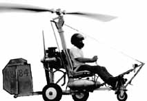
Page Content This page introduces viewers to today's Gyrocopter. Pictures show some mechanical details of this type aircraft. Simple explanations are included with each picture to aid in understanding what is being shown. This page was created using Microsoft Front Page. Some features, titles for instance, are not compatible with some other web browsers. Firefox is one example of lack of compatibility. |
 |
Page History Page Was Created: 04/09/98
|
 |
The forward section of the ship can be seen here in detail. A communications antenna is mounted on the front of the airframe. That is the long white rod extending down from the front of the airframe. Note the rudder peddle to nose wheel steering linkage, this is a well designed and built machine. This detail does not exist on some cheaper/simple aircraft. |
![[Logo 2]](images19/gyro2a.jpg) |
Where to put an instrument panel on a small machine like this is a problem. Manufacturers are making smaller gauges to help make smaller instrument panels possible. This package looks good and is robust. The box design provides weather proofing and protection from the Florida sun. |
![[Logo 2]](images19/gyro3a.jpg) |
Shown here is the Airspeed and Altitude Indicators. Information conveyed by these instruments is very important to a pilot, so these instruments are mounted at the top of the stack so they can be seen quickly. |
![[Logo 2]](images19/gyro4a.jpg) |
Other information needed is rotor blade RPM and engine RPM. Remember the engine does not directly connect to the rotor head as a helicopter's engine does. The rotor of a gyrocopter is rotated by the relative wind blowing across it. The relative wind is the apparent air movement caused by the gyrocopter passing through the air. When you hold your hand out of a car window while the car is moving and you feel the air rushing past you are feeling relative wind. |
![[Logo 2]](images19/gyro5a.jpg) |
Exhaust Gas Temperature is measured and so is fuel state. Various switches and controls are necessary to operate the machine. This aircraft is well instrumented. The aircraft Flight Control Stick (Joystick) is visible to the right of the instrumentation panel. The direction of vertical flight is controlled by tilting the rotor-head in the direction the pilot wishes to go. |
![[Logo 2]](images19/gyro6a.jpg) |
The propeller engine combination is light weight and produces high thrust. You can see the fuel air intakes wrapping over the top of the engine. The propeller is made of composite material and is more efficient and lighter weight than wooden or metal versions. The system is a pusher type in that the propeller is facing aft. Normally there is no direct connection between the engine and the rotor blades so no energy is directly transferred from one to the other. |
![[Logo 2]](images19/gyro7a.jpg) |
Fuel air intake system. This represents a tuned system. Carburetors are small but efficient. Air filters can be seen at the far ends of the intake system. |
![[Logo 2]](images19/gyro8a.jpg) |
Exhaust system is also a tuned system. The headers are manufactured to a size and shape that is determined by a math formula. This is done to extract the maximum power out of the small engine. This design process is not unlike the process that can be used to manufacture headers for use on automobiles. |
![[Logo 2]](images19/gyro9a.jpg) |
High Energy spark system is used to produce the electrical energy for firing the spark plugs. |
![[Logo 2]](images19/gyro10a.jpg) |
This is the rotor-head with its many moving parts. This assembly in no way approaches the complexity of a helicopter rotor-head. The two push rods to the left of the picture (aft of the mast head) control the tilt of the rotor-head. This tilt is the way the gyrocopter is directed in flight. The flywheel located below the rotor blades is used to pre-rotate the blades so that a much shorter take off distance is possible. |
![[Logo 2]](images19/gyro25a.jpg) |
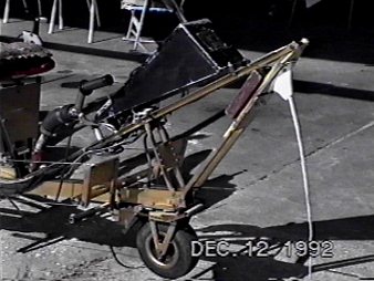
This aircraft has a tricycle landing gear configuration. This makes the aircraft easier to control on the ground than a tail wheel design. The rudder is mounted directly in the prop wash thereby providing strong control when the engine is producing power. In flight the rudder is used to control direction of flight much more than in a airplane. On the ground the rudder and differential braking is used to control direction of travel. |
![[Logo 2]](images19/gyro26a.jpg) |
A view of the pre-rotator. Power is supplied directly from the engine by providing a path for rotational energy to be transferred from the engine to the rotor-head. The tube between the engine and the blades has a rotating shaft in it and when the engine rotates the shaft at one end the other end of the shaft rotates the rotor blades. This is like a speedometer cable in a car. Pull a lever to engage the pre-rotor mechanism and the rotor blades are spun-up to take off speed so little or no take off run is required. |
|
|
|
|
|
|
|
|
|
|
|
|
|
|
|
|
Carter Aviation Technology We have no connection or involvement with the Carter Company |
|
| Web Page Created By Frank C. Odell Merritt Island, Florida, USA BOTTOM OF PAGE |
|