| Welcome to my 'Ampeg Amp' Page |
| Where I document the repair and modification of an Ampeg VT-22 guitar amplifier. |
 |
| First - the original schematics... The amp is a relatively newer model. You can look at these very old sche-magics if you want, the pre amp.gif, and the power amp.gif. from around 1972. The new power amp m8.gif schemagic!! I've been muckin' about with this for a while now, it's not complete, but it's a start! The main reason I am posting this page, is so that the owner of the amp can keep track of progress. He lives 2.5 hours from here! This amp is his 'baby' , and almost as important as his real baby, allthough not as cute!! :) Remove death cap. Install bias measuring, cathode, 1 ohm resistors. Test 'candy cane cap' since it appears cracked. (0.47uf) Seems OK. It drives the reverb tank. Replace burnt resistor visible on PCB, that runs the standby lamp. (R54). (It tests OK - will see...) Build back-up bias supply, because of weird Ampeg circuit, and install. Install bias adjust pots, modify bias arangement between output quad, similar to SVT. Install bias meter and switch, (hey - swap tubes at gigs, or match your own tubes!) Replace all 'lectrolitics. (cap job) Install 3rd speaker jack, 2 will be series for 2 x 4ohm cabs, 1 will be parallel for 1 x 8 ohm cab. All 3 used will be 4 ohms! Clean and adjust - inspect for water damage. Check amp operation and repair defects. Clean and repair the controls. The original speakers from this amp (2 x 12") were re-coned at aaahhhz.inc in Ontario. Build new cabinet to replace water logged old rotted out cabinet that looks like an old boat!. Replaced bad power cord. |
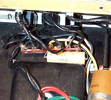 |
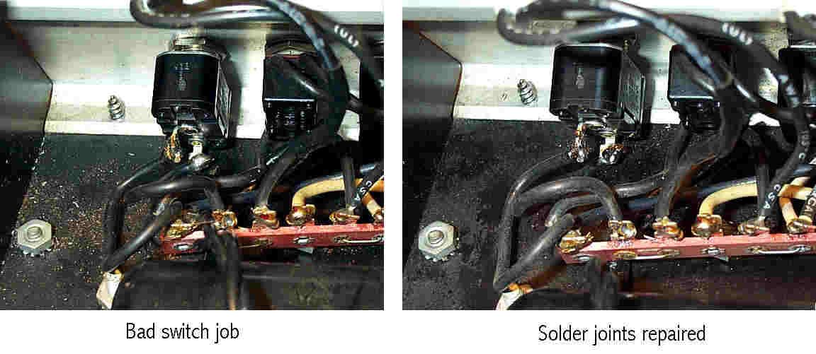
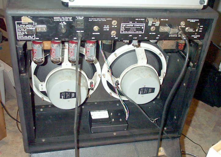
| April 2, 2001 OK - and we're off! All set up and ready to go. Luckily I found my BIG variac, and my BIG load resistor... now 'this' is a load resistor... The first thing - the 'death cap' !! These caps serve no purpose with 3 prong cords anyway, so, out it goes!! And right near it, someone had changed the power switch. Someone in need of a soldering course!! Well ok I cleaned that up in no time.. can I get some real work done now? Ok - how about installing the cathode measuring resistors? Who could tell if the factory didn't install this? (I used an Ampeg terminal strip!) I managed to put it in a good place to intercept the original ground wire - should be perfect! Well I've installed the 3rd speaker jack, now you can put anything you like! One speaker of 2, 4 or 8 ohm; 2 x 4 ohm; 2 x 4 ohm and 1 x 8 ohm... all your cabs! The only restriction is that the 'main' jack must always be used, since it 'shorts' the amp. |
| The white death cap |
 |
| A little cleaning... |
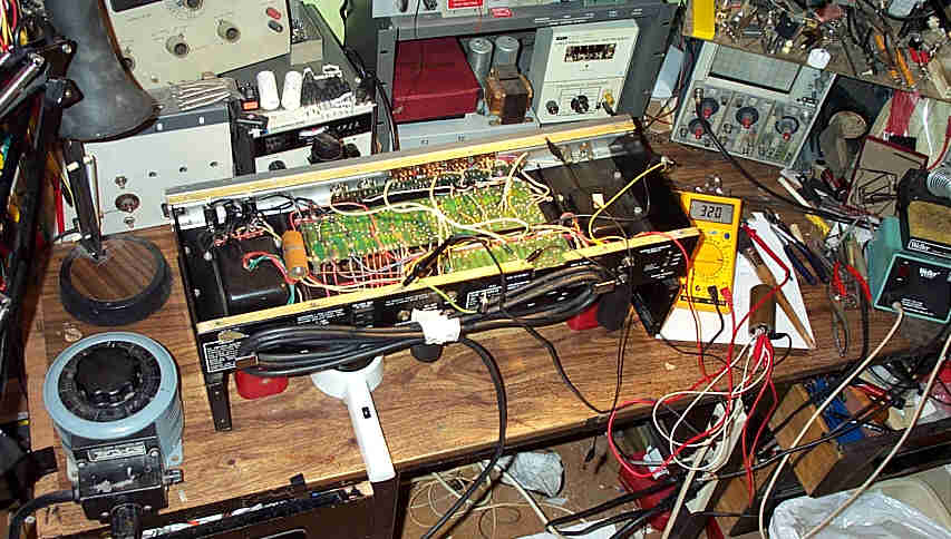 |
| Ready to start! |
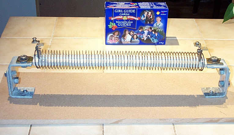 |
| Look up load resistor - you won't find this one! |
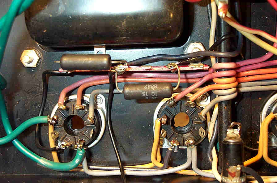 |
| Cathode measuring resistors |
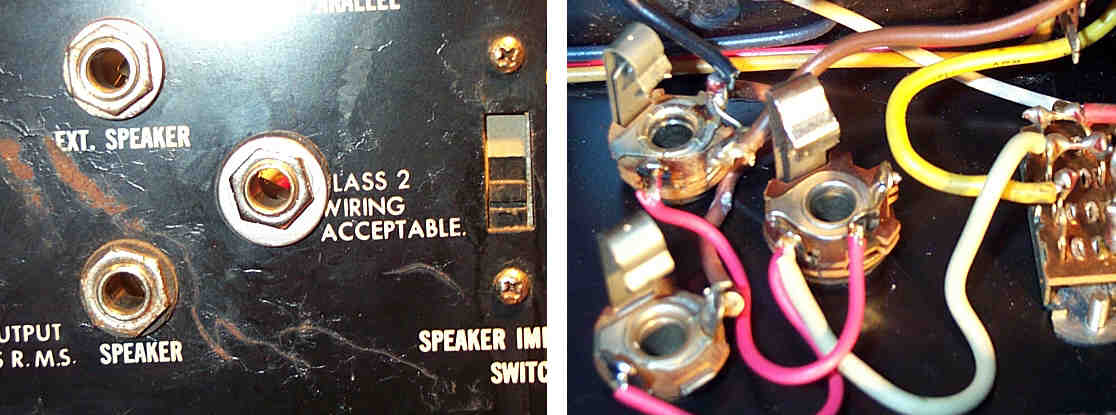 |
| Install a third spk jack, in series. |
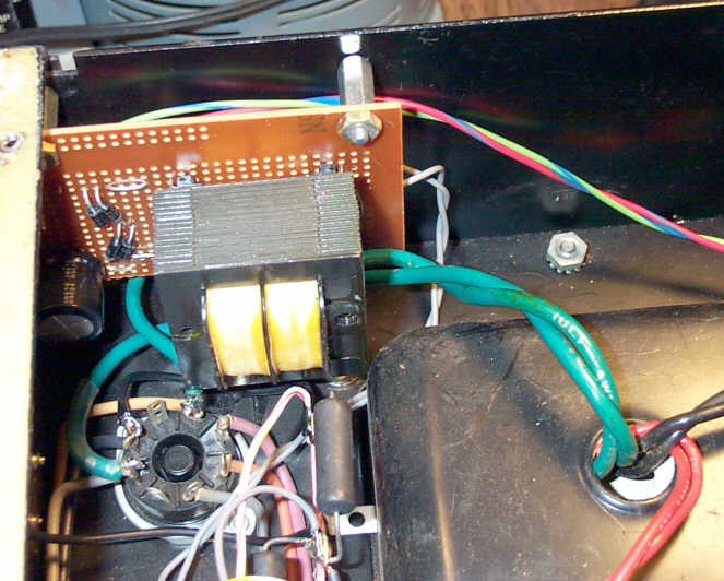
| April 15 , 2001 Well, it seems the caps will take a while to get here, so.... I will start on the bias meter and boost board. The boost is a circuit that takes some power from the filiment winding, steps it up to 60 VAC by sending it backwards through a 240/12 volt trannie, and then up to maybe -120 VDC thru a bridge, and then thru a pass resistor to add to the 'pool' of bias voltage developed by the Ampeg circuit. (I developed this mod-board to enable the addition of fixed bias to amps that don't have it.) The Ampeg circuit is a bit weird... because there is no center tap on the trannie, there can be no referance to get a neg voltage, so instead, the AC power is taken thru a capacitor, and rectified into neg DC, like an AM radio detector!! This is considered by some to be a possible source of trouble - if any one of the componants goes - the bias goes!! The supply is not "stiff", in other words, it is easily upset. Even the humidity can alter the bias setting. I'm not replacing it, since I HATE to do mods, I'm just adding to it. The only real mod will be the removal of the 2 bias sourcing resistors from the PCB, and the introduction of a dual pot adjustable circuit. |
| The meter, pots and switches, are mounted in an aluminum box, attached to the chassis. The hard part was cutting a big round hole for the meter!! Well, this $40 Milwaukee hole saw did the trick! The transformer will be mounted elsewhere. The meter is nice - a 100ma full scale Simpson Taut Band with a heart pointer.... the picture here shows it with its new face, which says DC Bias , 0 to 100 ma. I made the printed scale with my Canon printer after scanning the meter into the computer, and re-doing the numbers. |
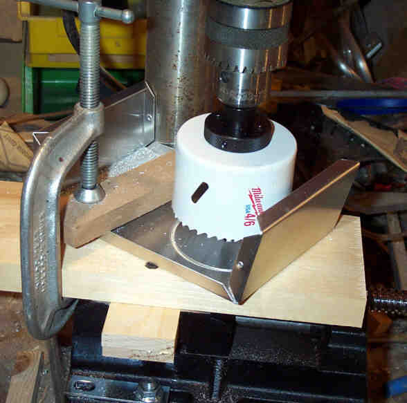 |
| Drilling a big hole for the meter. |
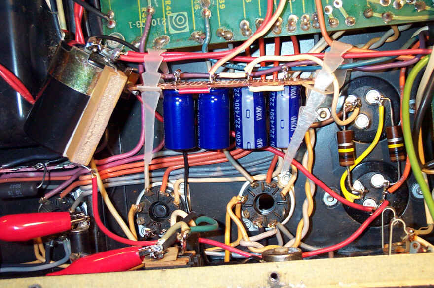
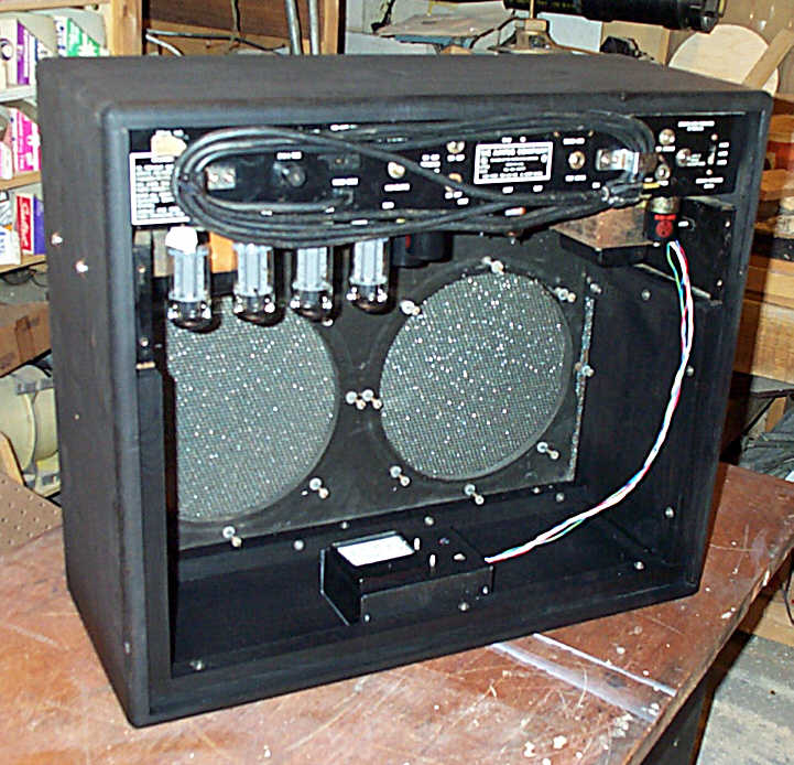
| April 25 , 2001 OK the caps have arrived!! I had to drill out the original mounts - rivets, you know... and use clamps to hold the new caps. The old ones were twist locks, mounted in fiberglass insolaters. I had to make 2 small changes, since 2 caps were 3 section and all I could get was 2 section... so I mounted one cap at the other side of the amp, along with its de-coupling resistor. The wires are shorter now, so it's a good thing... Also I had to make a small cap board to hold 4 caps in series parallel, to make up a 20mmf, 600v unit for the screen supply. It has 4, 22mmf@450 caps, and 2 resistors not used in the original design. I took a risk on the original order, and tried to get away with using a 100 in series with a 30, but it doesn't balance. No big deal, this is as per the original design, and is easier to place in the amp. And I already had the parts If you want information on re-capping a V-22 or V-4, check out my re-cap page. The 4 original cans are replaced with more easily found modern caps. The 100uf/450v caps MUST be power supply rated cans. The other caps can have a lessor ripple current rating. |
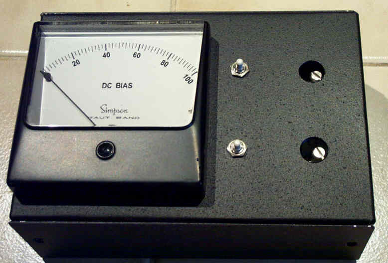 |
| Finished Bias meter |
 |
 |
| May 13 2001 Everything is almost finished, I'm presently testing the adjustable bias circuit and boost board, so I can pick the various resistor values. I want the pots to go from close to zero current bias, to a max of maybe 100ma per tube. This is too high, of course, but the range will be good for tubes that are weak as well. It should be able to bias ANY tube! Also I want it to operate in such a fashion that if the adjuster box gets knocked off the amp, or if its wires are cut, the amp will remain in fairly safe operation. ( Atually, it will revert to class 'B', still working, but sounding harsh.) |
 |
 |
| June 3 ,2001 All of the testing is complete - I've finalized all of the componant values. Now to just finish the little board and mount it. It's fun dialing in different bias's!! Can change the tone quite a bit. I showed a technician friend the amp - he says "Where'd you get the dinosaur!?" I said "This thing is 100 watts, watch this", and turned it on... he says, "It isn't working, I don't hear it." "Sure it is", I said, as I turned the sine generator on. . . Damn near blew him out of the room !! - "Quiet, eh?" I said.... This amp REQUIRES serious ear-protection! |
 |
 |
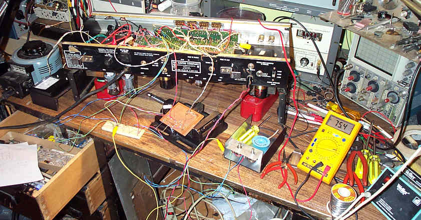
| Testing, testing. |
| The bias booster board. |
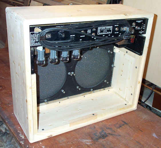
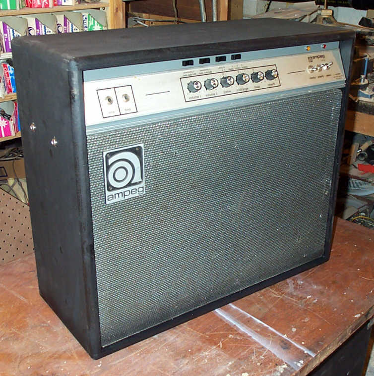
| The completed amp. |
 |
 |
 |
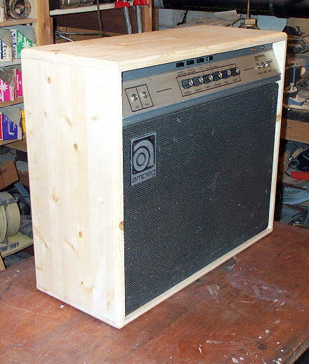 |
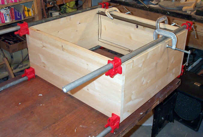
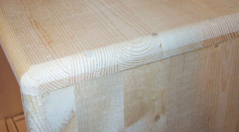
| June 21 ,2001 Well, the original cabinet is toast, so I built another one, an exact copy. Hey, I'm an Ampeg factory! Still have to do some work on mounting the bias meter, but it will be much easier to figure where now! July 12, 2001 A little black paint can do wonders... now as soon as I get some Tolex, and the speakers... It's so close to 'tone-city' I can't stand it!! July 13 2001 Well the speakers are in, and the amp's off to Ottawa!! It's been fun! |
 |
 |
 |
| ANOTHER Ampeg has arrived!!! This one is older, in worse shape, and is shown on another page... The Ampeg2 Page |