 |
|
| By
Doug Dixon
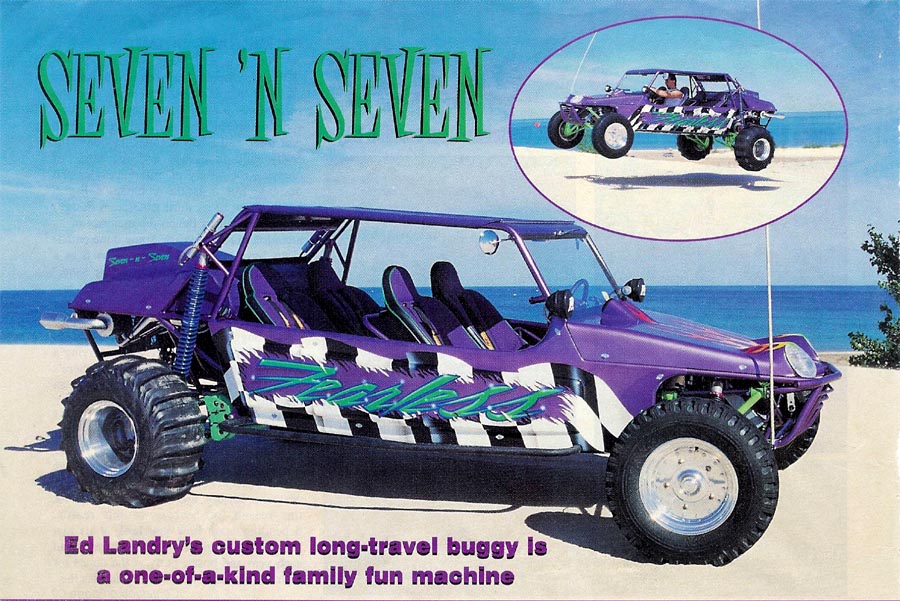
Every once in a while we run across a sand toy that is so unique, so vastly different than anything we've seen before, that we know right off the bat it belongs in the magazine. Such was the case with the buggy you see here, assembled by Ed Landry, of Bloomfield Hills, Michigan. At first glance you might think the only unique part of this car is the hand-formed carbon fiber body. But there's much more to it once we delve into the fine details. This project started with a four-seat, rear-engine chromoly chassis from Dan's Off-Road, in Hemlock, Michigan. But Ed, with a background in building concept cars for the big American auto makers, had a few "concepts" in mind for this buggy as well. How about two snowmobile engines, one powering each rear wheel? Or the fact that there's an onboard power-proportioning system for each engine/wheel depending on steering wheel angle? There's an on-board computer, dual custom made digital tachometers - not your average off-the-shelf buggy items. Looking at the basic chassis and suspension, it features a 119-inch wheelbase, with A-arm style front suspension and custom trailing arm rear suspension. The front arms were built by Dan's Off-Road, utilizing 1-1/4 inch chromoly tubing. Wright Combo spindles, urethane bushings at the inner pivots and King 2-inch coil-over shocks with an 8-inch stroke and dual-rate springs. This combination provides 17 inches of front wheel travel. Front rolling stock are Mickey Thompson off-road tires mounted to 15x5.25 CMS aluminum wheels. CNC front disc brakes ensure plenty of stopping power. Out back the suspension is unlike anything we've seen before. Actually, the concept is the same as a standard trailing arm suspension, but the execution is quite unique due to the one-off drive system. |
Ed fabricated
the rear arms himself, which have dual pivots and an outer bearing carrier
and stub axle assembly like many other designs. But that's where the
similarities end, as the axles and CVs do not connect to the outer stub
axles. Power from each engine travels through a 3/4-inch chain to a
sprocket attached to a stub axle that is in a bearing carrier solidly
mounted to the inner frame rails (confused yet?). There is no center
differential that connects the drivelines of both wheels. The left engine
powers the left wheel, and likewise the right engine powers the right
paddle tire. Now, connected to the inner stub axle on each side are CV
joints and axles taken from the front of a 1986 Chevy S-10 4x4. These are
located near the front of the trailing arms, and connect to the trailing
arms via another stub axle, which is mounted in a bearing carrier built
into the forward section of the trailing arms.
|
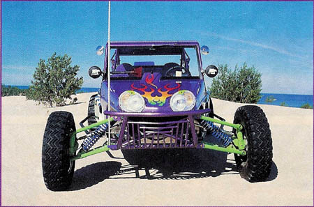
| TOP, we photographed Ed's buggy at the beautiful Silver Lake Sand Dunes, with Lake Michigan providing the backdrop. ABOVE, the carbon fiber body was hand laid by Ed after he carved the molds out of styrofoam. The unique headlights/turn signals are from a 2001 Bombardier golf cart. | |