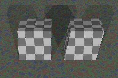
A normal cube and a sheared cube.
One of the most esoteric features of POV-RAY is the matrix transformation. While in the strictest sense it is redundant--all of the functions performed by the matrix can be duplicated with the right combination of rotates, scales, and translations--certain operations are much easier with the matrix.
Matrices, like other transforms, can stretch objects, spin object, move objects, and distort them in a particular way known as the shear. Any linear transformation, or combination of linear transformations, can be done with a matrix.
From time to time, new users of POV-Ray commonly ask if there is a way to stretch an object by different amounts along an axis. Matrices cannot turn a cylinder into a cone, or perform any other non-linear transformation.
The statement expected by POV-Ray looks like this:
   matrix < Ax, Ay, Az,
            Bx, By, Bz,
            Cx, Cy, Cz,
            Dx, Dy, Dz >
Internally, a fourth column is supplied by POV-Ray, for the purposes of its internal matrix operations. The result looks like this: matrix < Ax, Ay, Az, 0,
Bx, By, Bz, 0,
Cx, Cy, Cz, 0,
Dx, Dy, Dz, 1 >
The matrix can look pretty imposing if you're not familiar with it, but here's the simplest explanation I can think of:
Think of the example matrix above as consisting of four vectors <Ax,Ay,Az>, <Bx,By,Bz>, <Cx,Cy,Cz>, and <Dx,Dy,Dz>. I'll call them A, B, C, and D. Now imagine that you are standing at <0,0,0> in one of your POV scenes, with your right arm stuck in the +x direction, up is the +y direction, and your face in the +z direction. If the matrix above were applied to you, your right arm will then point along vector A, your head will be pointed along vector B, your face will be towards vector C, and your feet will be moved to D. This is how I think the numbers through when I'm constructing matrices for POV-Ray.
If the three vectors A, B, and C are all perpendicular to each other (that is, they meet at a right angle), the matrix will have the effect of a scale, a rotate, and a translate, performed in that exact order. This is the order of transformations that is most common in modeling software. If the vectors are not all perpendicular, then the result is a sheared object. Shearing is hard to describe in words, so here's a picture:
All of the tranforms commonly used in POV-Ray are converted to the matrix form internally. This allows POV-Ray to use one process for dealing with changes to an object, instead of several different processes (which would all need to be separately debugged if they didn't work properly).
Translation: Translation is the simplest of the transforms to understand. It simply moves the object. The POV-Ray statement
translate <Tx,Ty,Tz>is converted by POV-Ray into this matrix:
   matrix <  1,  0,  0,
             0,  1,  0,
             0,  0,  1,
            Tx, Ty, Tz >
Scaling: Scaling shrinks or expands an object. The POV-Ray statement
scale <Sx,Sy,Sz>is converted by POV-Ray into this matrix:
   matrix < Sx,  0,  0,
             0, Sy,  0,
             0,  0, Sz,
             0,  0,  0 >
Rotation: Rotation spins an object around the three axes. POV-Ray expects a vector as the argument for rotation, and so the supplied vector actually provides for three separate rotate actions. The x-component of the vector specifies the amount of rotation, in degrees, around the x-axis. The y-component of the vector specifies the amount of rotation around the y-axis, and the z-component specifies the amount of z-axis rotation. When rotations are supplied as a vector, the x-rotation is done first, then the y, and then the z. The POV-Ray statement
rotate x*thetais converted by POV-Ray into this matrix:
   matrix <  1,  0,  0,
             0,  C,  S,
             0, -S,  C,
             0,  0,  0 >
where C equals the cosine of theta and S equals the sine of theta. Likewise,
rotate y*thetais converted into
   matrix <  C,  0, -S,
             0,  1,  0,
             S,  0,  C,
             0,  0,  0 >
and
rotate z*thetais converted into:
   matrix <  C,  S,  0,
            -S,  C,  0,
             0,  0,  1,
             0,  0,  0 >
Shearing: Shearing is a transform that distorts the shape of the transformed object in a non-orthogonal way. The easiest shear matrix to construct works by shifting the object by a certain amount for every unit amount moved along one of the axes. For instance, this matrix
   matrix <  1,  0,  0,
             0,  1,  0,
            .2,  0,  1,
             0,  0,  0 >
will distort an object so that for every unit the object extends in the z-direction, the object is sheared by .2 in the x-direction. This is how the sheared cube above was produced. I didn't have to shear in just the x-direction when I wrote this matrix. I could also have sheared in the y-direction (causing it to slope towards or away from the camera), or in the z-direction (causing the cube to be stretched in the z-direction as well as being sheared), or any combination of the three.
A more generalized matrix,
   matrix <  1,  0,  0,
             0,  1,  0,
             U,  V,  1,
             0,  0,  0 >
will cause the object to be sheared by U in the x-direction and V in the y-direction for every unit along the z-axis. Likewise, matrix < 1, 0, 0,
U, 1, V,
0, 0, 1,
0, 0, 0 >
will shear objects by U in the x-direction and V in the z-direction for every unit along the y-axis, and matrix < 1, U, V,
0, 1, 0,
0, 0, 1,
0, 0, 0 >
will shear objects by U in the y-direction and V in the z-direction for every unit along the x-axis.
Combining matrices: Matrices can be multiplied together, according to particular rules. When two transformation matrices are multiplied together, the result is a new transformation matrix that has the same effect as the two original matrices applied in succession. POV-Ray uses this capacity to combine all of an object's transforms into one final transformation matrix. This combination is done during parsing, so that an object that is transformed a hundred times renders as quickly as an object transformed once.
Rotating from one vector to another: Suppose, for example, that you have an object at location V1, and you want to rotate it around the origin so that it winds up at V2, (presuming that V1 and V2 are the same length), and so that the object turns a little bit in addition to being moved. To do this with rotates would be a small nightmare to calculate (and I'm not going to try it), but with the matrix it's easy:
  #local VX1=vnormalize(V1)
  #local VX2=vnormalize(V2);
  #local VY=vcross(VX2,VX1);
  #if (vlength(VY)>0)
    #local VY=vnormalize(VY);
    #local VZ1=vcross(VY,VX1);
    #local VZ2=vcross(VY,VX2);

    matrix < VX1.x, VY.x, VZ1.x,
             VX1.y, VY.y, VZ1.y,
             VX1.z, VY.z, VZ1.z,
                 0     0      0 >

    matrix < VX2.x, VX2.y, VX2.z,
              VY.x,  VY.y,  VY.z,
             VZ2.x, VZ2.y, VZ2.z,
                 0,     0,     0 >

  #end
Note that to rotate in this manner both matrices are required and they must be used in the order shown here. I could have combined them together into one matrix, but that would involve much more typing than what you see here (and more chances for a typo to screw things up).
Rotating around an arbitrary axis: The standard rotate transform rotates around the x, y, and z axes. It is possible, however, for the axis of rotation to lie along any vector, and not just the major axes. The vaxis_rotate(A,B,f) function allows you to rotate a point around any axis, but there is no standard transform for such an operation on an object. A couple of properly-designed matrices and a snippet of scene code will do the trick:
  #local VX = vnormalize(V);

// assuming that V is the axis of rotation

  #local VY = vnormalize(vcross(VX,<VX.y,VX.z,-VX.x>));
  #local VZ = vnormalize(vcross(VX,VY));

  object { MyObject

  matrix < VX.x,VY.x,VZ.x,
           VX.y,VY.y,VZ.y,
           VX.z,VY.z,VZ.z,
              0,   0,   0 >

  rotate x*Angle // here Angle is your angle of rotation

  matrix < VX.x,VX.y,VX.z,
           VY.x,VY.y,VY.z,
           VZ.x,VZ.y,VZ.z,
              0,   0,   0 >
  }
A handedness flipper matrix: One of the problems experienced by POV-Ray users is the problem of handedness. POV is written with the assumption that when x is to the right and y is up, z will be into the screen. This is known as a left-handed coordinate system; by pointing the left thumb in the x-direction, the fingers of the left hand curl from the y direction to the z direction.
Some modelers, on the other hand, assume that z is up and y is forward. This switches the y and z axes, and changes things from left-handedness to right-handedness. Everything designed for a left-handed scene will appear as a mirror image of itself in a right-handed scene.
Most modelers deal with this by rotating and mirror-image scaling the obejcts that need to be re-oriented, but a matrix can do the swap in one step:
matrix < 1,0,0, 0,0,1, 0,1,0, 0,0,0 >
This matrix transform will change a left-handed item into a right-handed one, and vice-versa. If you compare it to the matrices at the beginning of this page, you'll see that all it does is point the y-stuff in the z-direction, and the z-stuff in the y-direction.
You can also use the handedness swap for re-orienting lathe, prism and tori objects. POV-Ray creates these objects with the central axis along the y-axis; if you want them pointing along the z-axis instead, this matrix will do the trick.
If you find yourself swapping axes a lot, you can declare these matrices as transforms:
  #declare SwapXY = transform { matrix < 0,1,0, 1,0,0, 0,0,1, 0,0,0 > }
  #declare SwapXZ = transform { matrix < 0,0,1, 0,1,0, 1,0,0, 0,0,0 > }
  #declare SwapYZ = transform { matrix < 1,0,0, 0,0,1, 0,1,0, 0,0,0 > }
and later use them in this way: object { MyObject transform SwapXY }
object { MyObject transform SwapXZ }
object { MyObject transform SwapYZ }
Know the vector, don't know the angle Another situation where the matrix is useful is when you already have a vector along which an object is to be oriented, but don't know the angle of this vector. You can use POV-Ray's built-in trigonometry functions to find the angle and feed the angle to the rotation transform, but it is usually simpler to put the vector components into the matrix. For instance, if you have designed a gun with the barrel pointing in the y-direction and the grip pointing in the z-direction, and you want the gun to be located at point L, be aimed at point T, and have its grip pointed down as much as possible, you can do one of two things:
#local AngleX = degrees(atn((T.z-L.z)/vlength(<T.x,T.y,0>-<L.x,L.y,0>));
#if (T.y>L.y)
  #local AngleZ = degrees(atn((L.x-T.x)/(T.y-L.y)));
#end

#if (T.y<L.y)
  #local AngleZ = degrees(atn((L.x-T.x)/(T.y-L.y)))+180;
#end

#if (T.y=L.y)
  #if (T.x>L.x)
    #local AngleZ=-90;
  #else
    #local AngleZ=90;
  #end
#end

object { Gun rotate <AngleX,0,AngleZ> translate L }
or you can do this instead:
#local NY=vnormalize(T-L);
#local NX=vnormalize(vcross(NY,z)); // z is down in this example
#local NZ=vcross(NX,NY);
object { Gun matrix < NX.x,NX.y,NX.z, NY.x,NY.y,NY.z, NZ.x,NZ.y,NZ.z, L.x,L.y,L.z > }
The first approach has a lot of #if statements to check for conditions under which the general trigonometric formulas don't work. The second approach works for all of these conditions without the error-checking. Note that when the gun points straight up or down, the requirements don't explain which way the grip is supposed to point, and consequently neither approach works.
The saddle: The saddle, also known as a hyperbolic parabola, allows one curved surface to connect four points, in the same way that a triangle can connect three points. To calculate the saddle required for any four arbitrary points, and to clip it so that it doesn't extend beyond the area it's intended to cover, would involve a large number of calculations. With a matrix you can use a pre-determined shape and transform it to fit.
As with most user-defined objects in POV-Ray, the best way to make regular use of them is through an .INC file. For the saddle, the .INC file would look like this:
// include file to generate the saddle shape
// before invoking this file, the user must define
// SaddleA, SaddleB, SaddleC, SaddleD as four points,
// in clockwise or counter-clockwise order
// so that SaddleA and SaddleC are on opposite corners

#local SaddleX=(SaddleA-SaddleB-SaddleC+SaddleD)/4;
#local SaddleY=(SaddleA+SaddleB-SaddleC-SaddleD)/4;
#local SaddleZ=(SaddleA-SaddleB+SaddleC-SaddleD)/4;
#local SaddleM=(SaddleA+SaddleB+SaddleC+SaddleD)/4;

quadric { <0,0,0>,<1,0,0>,<0,0,-1>,0
  hollow
  clipped_by { box { -1,1 } }
  bounded_by { clipped_by }
  matrix < SaddleX.x,SaddleX.y,SaddleX.z,
           SaddleY.x,SaddleY.y,SaddleY.z,
           SaddleZ.x,SaddleZ.y,SaddleZ.z,
           SaddleM.x,SaddleM.y,SaddleM.z > }
//end of include file
To use it, the user would employ the following code:
// example of saddle.inc file usage

#declare SaddleA=<0,0,7>
#declare SaddleB=<0,-7,0>
#declare SaddleC=<7,0,0>
#declare SaddleD=<0,7,0>

object { #include "saddle.inc" texture { MyTexture } } // whatever floats your boat
// end of example