Next, install a LED to tube socket pin A8 to G, with silver paint facing the ground plane, and the other LED to tube socket pin B8 to P, with silver paint facing the ground plane.
I have also installed the two 0.47uF(474) caps from terminal 32 to RCA out center, terminal 42 to RCA out center.
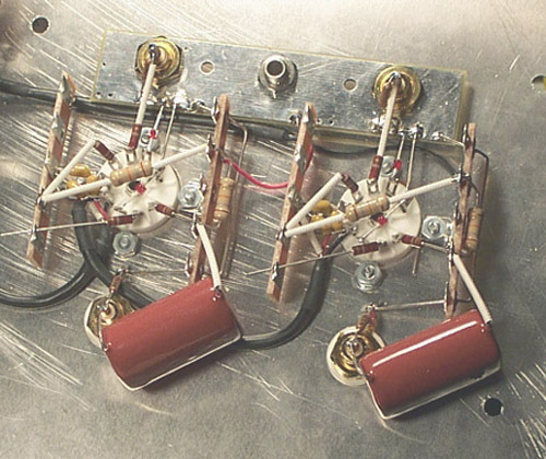
Next came the RIAA network resistors(refer to page 35). Install a 1Meg resistor from terminal 26 to ground plane, another 1Meg resistor from terminal from 36 to ground plane also.
Next, connect a 66.5K resistor 27 to 29, another from 37 to 39, respectively.
Now comes a 9.31K resistor from terminal 29 to 30, another 9.31K from terminal 39 to 40, respectively.
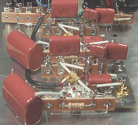
(Refer to page 36) next, install a 0.1uF(104) from 26 to terminal 29, another 0.1uF from 36 to terminal 39.
Now follow with the two 0.012uF (122) caps: one from terminal 29 to ground plane D, another from terminal 39 to ground plane M.
Next, install those 0.01uF (103) from terminal 29 to ground plane, another from terminal 39 to ground plane.
Now, install 0.033uF (333) from terminal 30 to ground plane, another 0.033uF from terminal 40 to ground plane.