CONTENTS

1.    INTRODUCTION
2.    ELECTROMAGNETIC THEORY
      2.1    Magnetic Field Calculation Theory
             2.1.1   Single Line Computation
             2.1.2   Multiple Line Computation
             2.1.3   Total Induced Current density at a Point
3.    PROGRAMMING
      3.1    FORTRAN and N88BASIC Programming
             3.1.1    Initialization and Input Data Part
             3.1.2    Assigning Position and Phase Angles of Line Currents
             3.1.3    EMF Calculation Part
             3.1.4    Output Part
      3.2    FORTRAN & N88BASIC Comparison
      3.3    VISUAL BASIC
4.    MFTL SOFTWARE
      4.1    Program Flow
      4.2    System Requirements
             4.2.1    Minimum System Requirements
      4.3    Added Features
      4.4    Functions and Sub Routines
      4.5    Control Flags
      4.6    Frames/Forms
             4.6.1    Input Frames
             4.6.2    Output Frames and File Management
             4.6.3    MFTLInfo, Navigator and Language Frame
5.    MAGNETIC FIELD UNDER OVERHEAD TRANSMISSION LINES
      5.1    Transmission Line Model
      5.2    Adapted Calculation Conditions and Methods
      5.3    Calculation Results
      5.4    Discussion of Results
6.    CONCLUSION
      References
      Acknowledgements
      Appendix
1. INTRODUCTION
Over the past few years, heightened coverage by the popular press has fueled interest in the health effects related to EMF exposure[1]. Researchers around the world are intensifying efforts to better understand EMF sources and levels, to investigate hypothesized mechanisms of biological interactions, to examine possible health effects of EMF exposure, and to identify methods for managing magnetic fields. With this scientist and engineers alike are looking for a tangible proof relating the EMF exposure to health associated disorder through continuous research.
Instruments for measuring the EMF exposure alone will not be sufficient. Computerized theoretical models of field distributions and exposures are also necessary. Conductor configurations in transmission lines should be investigated for the development of field reducing utilities if EMF exposure proves to be a biological hazard in the future.
A lot of programs have been developed for the calculation of field distribution, though they use a separate software in viewing the calculated results. And most of the time, these programs provide information that is difficult for a non-technical person to understand. With this, we are developing a user-friendly, Graphics User Interface (GUI) software for the calculation of magnetic field (MF) distribution under the vertical-type transmission line[2]. This software seeks to provide research scientist a theoretical calculation of the magnetic field distribution as well as the common people.
In the calculation, some factors has been neglected for they provide no or little effect in the MF magnitude and phase angle calculation. These factors will be discussed in the preceding chapters of this paper.
This self-installing software will provide the users the field's magnitude and phase angle calculations of a vertical-type 2-circuit transmission line 50-meter extending from left to right. A vertical-type configuration is used because this is the configuration commonly used in Japan. It also allows the user to save, print the calculated data and to graph the data.
2. ELECTROMAGNETIC THEORY
2.1 Magnetic Field Calculation Theory
2.1.1 Single Line Computation
Magnetic flux is produced when an alternating current is passed through a wire. Flux density is the flux produced per unit area. To conform with other research paper, magnetic flux density is also expressed as the magnetic field.
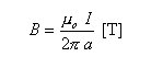
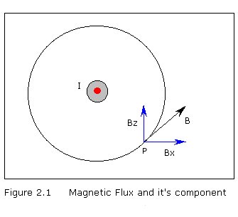
By Biot-Sabart's law, magnetic flux density B at point P in Figure 2.1 produced by an infinite straight conductor, a distance away from the line current is expressed by the equation[3] :
Thus Bx and By, and can also be computed using the following equations :
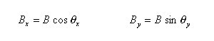
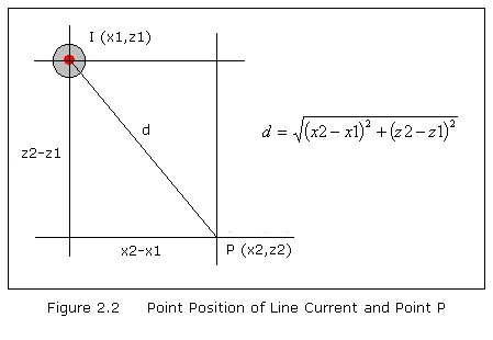
Note that the trigonometric functions are calculated using the point position of the line current and the point P as shown in Figure 2.2.
2.1.2 Multiple Line Computation
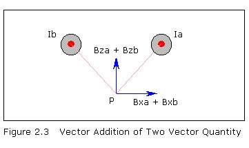
Since the power transmission line consists of 6 lines, summation of the magnetic fields by each line currents must be repeatedly calculated at different points P. Since the magnetic field is a complex vector quantity, components on each axis should be added vectorially. Figure 2.3 shows a vector addition of 2 vector quantity.
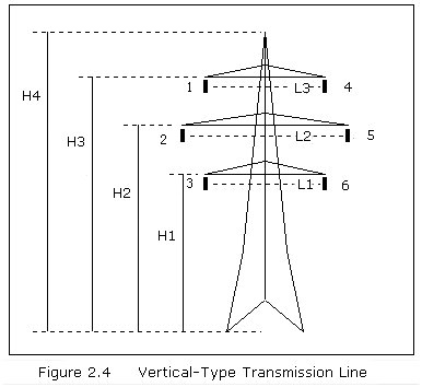
A vertical-type transmission line has 6 line currents (Figure 2.4) that should be taken into account when computing for the magnetic field.
2.1.3 Total Magnetic Field at a Point
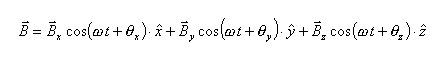
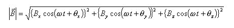
The total magnetic field density is a complex vector quantity and is expressed by the equation[4]
3. PROGRAMMING
3.1 FORTRAN and N88BASIC Programming
Two of the most used DOS-based programming language are FORTRAN and N88BASIC. FORTRAN is a programming language that can handle all levels of mathematical operations. Making it the most used language involving complex mathematical calculations. On the other hand, N88BASIC, the NEC's own version of the BASIC language, is the most easiest language to program. Although, unlike FORTRAN, it cannot handle complex mathematical operations in a single command.
The whole program is divided into four parts - the Initialization & Data Entry part, the Line Current Information Assignment part, the EMF Calculation part and the Output part.
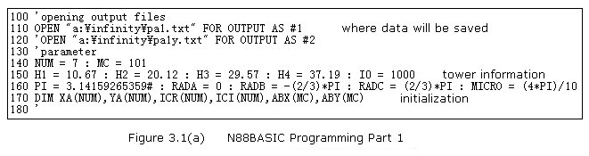
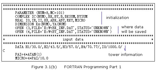
3.1.1 Initialization and Input Data Part
Memory reservation and data value initialization takes place. Constant values that will be used throughout the program is also declared in this part (Figure 3.1).
3.1.2 Assigning Position and Phase Angles of Line Currents
The information regarding the line currents are assigned to their respective variables in Part 2 of the program (Figure 3.2). These values are necessary for the computation of the magnetic field (MF) intensity and phase angle, the third part of the program. These information includes the phase angle of the current passing through the line as well as the position of the line.
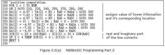
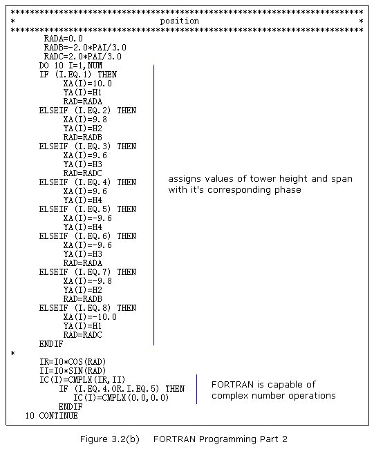
The line current is also expressed as a complex number IC in FORTRAN and real ICR and imaginary ICI number in BASIC. Since the MF is directly proportional to the line current and the line current is a complex number, then MF value is confirmed to be a complex number.
Since there is no complex operation in BASIC. The real and imaginary number can be computed using the trigonometric (Sine and Cosine) function.
The FORTRAN Program utilizes the If...Then command while On...Goto command in the BASIC program. In the If...Then statement, the program will go through all the condition whereas in the On...Goto statement, it will only go to the target line number.
The On...Goto command compressed the program by half, though the execution time is the same. There will only be a difference in the execution time, if there will be more conditions present in the statement.
3.1.3 EMF Calculation : Heart of the Program
This is the heart of the program (Figure 3.3). This is where the task is being carried out - the calculation of the magnetic field. EMF distribution is evaluated from 101 (MC=101) different point P. With the center of gravity of the post plus 50 meters extending from left and another 50 meters from the right makes it all 101 different points at 1-meter level (YY=1) above the ground.
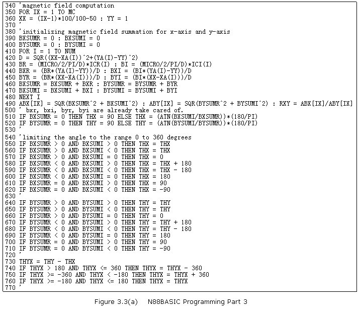
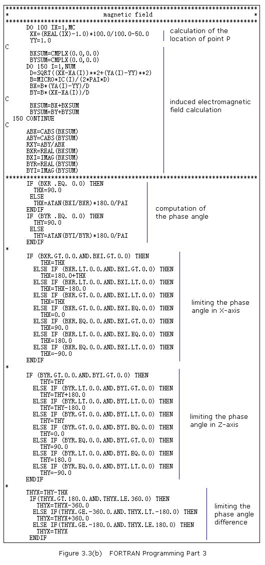
The summation of BX is taken by BXSUM, while BY by BYSUM. Again, these two quantities are vector, therefore the BASIC equivalent is separated into two - the real and the imaginary part.
The phase angle is computed using the inverse tangent function. The inverse tangent function yields an answer from 0 to positive infinity. For this we have to limit the value of the angle within the range 0 to 360 degrees. Angle Z minus angle X describes the phase angle difference.
The BASIC program is exactly the same as that of the FORTRAN program provided that it used additional variables to obtain the required quantity.
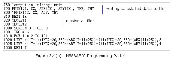
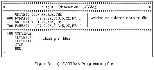
3.1.4 Output Part
Output part (Figure 3.4) consists of writing the calculated data into a file in both programming. Though in Basic programming, a simple presentation of results was included. For this, the Line command is used in plotting the curve.
3.2 FORTRAN & N88BASIC Comparison
There are a few changes or features that have been incorporated in changing from FORTRAN to BASIC program. Table 1 shows the summary of the changes/features in each programming language.
Complex Number Operation. FORTRAN can handle all mathematical operations including operations regarding complex numbers. Since there is no straight-forward command or operation for complex numbers in BASIC, additional middle-variables are incorporated to obtain the needed quantity.
Visual Presentation. A good and simple visual presentation of the results is needed to be able to study the distribution of the EMF in a vertical-type transmission tower. The FORTRAN program didn't include any visual presentation within the program itself. This is probably because graphics in FORTRAN programming is complicated compared to the BASIC programming. Most of the time, another application is used for the graphics presentation when using the FORTRAN language. BASIC program, on the other hand, has a very simple visual presentation. Line command with color representation is used to achieve this feature.
TABLE 3.1 A quick summary of the Change/Features
| DONN | FORTRAN | N88BASIC |
| Complex Number Operation | Automatic. FORTRAN can handle operations on complex numbers. | Not Automatic. N88Basic does not have any operation involving complex numbers. |
| Visual Presentation | No Visual Presentation. Uses separate application for data presentation. | Simple Visual Presentation. User has option to use another application for data presentation. |
3.4 Visual Basic
Visual Basic (VB) is the popular language used in software development in the Windows operating system. Visual Basic is a Graphic User Interface (GUI) Basic programming language which can only be utilized in the said operating system[5]. Windows is the commonly used environment for computers today. With the new VB4 and VB5, anyone can make professional programs instantly in the today's commonly used environment.
VB and Basic are the same though some of the commands were modified. VB involves not only basic programming but also the frame design. Aside from the Basic language commands, VB added more terminology; VB event, property and control. Also, VB utilizes some of Windows predefined dialogue boxes and controls making it more convenient for the user.
In order to use the Basic program in the windows environment, it must be reprogrammed to run under the Visual Basic language. The details of the MFTL program will be discussed thoroughly in the succeeding chapters. Microsoft Visual Basic 4 programming language is used in the program.
4.1 Program Flow
Basically, the program flow as shown in Figure 4.1, is like a common calculating program; from initializing the variables and memory and input of required information to calculation and printing out of calculated data. Though some special features were added to facilitate the users demand. These includes saving and printing of initial information, calculated data and graphical analysis.
MFTL Program starts by checking the registration file which only goes with a registered version of the program. If this file exists, then the user will be asked to choose the program language. On the other hand, if the file doesn't exists, program features will not be accessible for use.
The user will then need to input the tower and line current information. Thus, the main control window and the input windows follow next. The program will then check for the validity of the information entered. If all information are valid, then it will proceed to the calculation of the MF distribution. Otherwise, an error message will appear and the program will not proceed to the operation/calculation.
There are two output possibilities that the user can choose from. The user can either save the calculated data to a file or print it out. The graphical analysis (MF distribution) can also be printed out.
4.2 System Requirements
4.2.1 Minimum System Requirements Table 4.1 shows the computer's minimum requirements for the program to run smoothly.
The program was made using Microsoft's Visual Basic 4.0 (Japanese Version) and is 32-bit compiled under Windows 95 environment. Thus, requiring the files in their specified directory shown in Table 4.2
| Platform | PC compatible |
| Operating System | Windows 95 |
| RAM | at least 16MB |
| HD free space | 400KB |
| Software | Visual Basic 4 (Japanese) |
| Desktop Screen Size | 1152 X 864 pixels |
| Video Adapter | 256 colors or above |
| Input Device | Keyboard and a mouse or a compatible pointing device is recommended |
| Printer | Color Printer is highly recommended |
Table 4.2 Other Required Files
| Path : drive\windows\system\ | ||
| Advapi32.dll Atok11de.dll Atok11w.ime Cmdlgjp.dll Comctl32.dll Comdlg32.dll Comdlg32.ocx Gdi32.dll Imm32.dll Indicdll.dll |
Kernel32.dll Linkinfo.dll Mpr.dll Msnet32.dll Msshrui.dll Msvcrt20.dll Msvcrt40.dll Nwnet32.dll Ole32.dll Oleaut32.dll Olepro32.dll |
Rpcrt4.dll Shell32.dll Svrapi.dll User32.dll Vb40032.dll Vb4jp32.dll Version.dll Winmm.dll Winnls32.dll Winspool.drv |
| Path :drive\just\jslib32\Jstxi.dll | ||
| Path : drive\tools_95\Imghook.dll | ||
4.3 Added Features
Bilingual Capability: The MFTL program serves both the Japanese and English-speaking users.
Save and Open Text Files: Calculated results can be saved as a text file for users' personal purpose. These saved files can also be opened for viewing purposes.
Automatic Installation: When installed, the program will be stored in the Program Files directory and is automatically included in the Start Menu Program Folder.
Hard Copy: User can obtain a hard copy of initial information, the calculated data and graphical analysis (magnetic distribution).
4.4 Functions and Sub Routines
Functions and Sub Routines were used to conserve memory usage during execution[5]. The legends shown in Table 4.3 will be observed throughout the discussion of chapter 4.4.
| Legends | Legend Description |
| Header( ) | Function/Sub Routine Name |
| A:\Windows\System | Drive/Directory Path |
| WindowName | Frame/Window Name |
| Fstring$ | Variable Name |
| filename.ext | FileName with Extension |
FileDrive( ) is a function that checks for the users windows directory. It gives an integer function defining the ASCII number of the hard drive. The trick here is that it checks the config.sys of the system. With this, we assume that the drive of the config.sys file is also where the Windows\Program Files directory is located.
Header( ) is a local sub routine for printing out headers with outTitle as the head title for that particular printout.
registerfile( ) is a local sub routine that checks for the registration file MFTL32.dll in the Windows\Program Files directory. If the registration file is not present, the user will be asked to input the registration number and then proceed to the main program. If invalid registration number is entered or no registration file is located, then some of the functions will not be available.
Unregistered Version: This is a version where 'UNREGISTERED' sign is written throughout during the program run. Printing and saving functions will not be available.
Registered Version: This version is the fully working version of the software. Registration can be acquired through Matsumoto Laboratory, Anan College of Technology, Anan-shi, Tokushima, 774-0017 Japan.
readfile( ) is a function that checks for the presence of a file as defined by the variable filename$ in the users computer. RegPath defines the actual path with the filename. This function gives out a string which defines the content of the first line of the file.
GetPosition( ) is a function that gives out an integer which defines the position where the string LString will be printed out at the center of the page.
LSelect( ) is a local sub routine that checks the condition of the program. SFlag is 0 if the MFTLInfo is in it's first execution else 1 if it is not.
outgraph( ) is a local sub routine for printing of data and graph as well as saving and viewing them.
Data: Term referred to as the calculated results of the program.
Graph: Term referred to as the plotted representation of results.
Saving Data: Saving of calculated results in text format.
Viewing Data: Writing of calculated results in a list box of ViewData.
PhasePS1( ) and PhasePH2( ) are local sub routines that computes for the phase angles and their difference and then plots a continuous curve at PSheet1 and PSheet2 respectively.
GraphMS1( ) and GraphMS2( ) are local sub routines that computes for the induced electromagnetic field's magnitude and then plots it at MSheet1 and MSheet2 respectively.
CheckLCurrent( ) is a function that validates the user-entered values for the line current. Since the Val command is used in checking, formatted entry will not be read as it is. Only the preceding numerical value will be accepted. Say, the user entered the value 1,000, the computer will read this value as 1 and not as 1000. The comma ',' is not considered as a numerical character.
DrawTower( ) is a sub routine that draws a simple ideal image of the transmission tower at the TowerData frame.
InitialPrint( ) is a local sub routine that printouts the tower and line current information as entered by the user in the TowerData and the PAlign input frames.
Main( ) is the starting sub routine of the program.
MainWindow( ) is a local subroutine that calls the Navigator, TowerData and PAlign frames to be shown.
Adata( ) is a local sub routine that assigns the tower information to it's respective variable.
PAssign( ) is a local sub routine that assigns the line current information to it's respective variables.
GetVersion( ) is a function that give a string value which defines the version number of the software which is used in MFTLInfo frame. The version information consists of the major, minor and a revision number which is automatically incrementing with respect to the number of times the program is revised by the programmer.
ViewTitle( ) is a function that returns a string that defines the title in the ViewData window.
WayOut( ) is a sub routine that ends the program in a proper way.
4.5 Control Flags
Several control flags have been used in the program. These are used to facilitate control over certain conditions within the programming. Below are the control variables used.
Japanese Language Flag (JFlag). Used to determine the language chosen by the user. If JFlag = 1 then the software will be in Japanese language, otherwise, it will be in English.
Printer Control Flag (PFlag). Used to determine if the output path of the operation. If PFlag = 1 then the result of the operation will go to the printer else it will be saved as a text file.
Data Control Flag (DFlag). Used to determine whether the data required is the calculated data or the graphical analysis of the calculated data.
Start Condition Flag (SFlag). Used to determine whether the program is in it's starting condition. This is special control flag used only for the MFTLInfo frame to lessen the number of used frames in the program.
4.6 Frames/Forms
4.6.1 Input Frames
Input windows is where the tower and line current information is defined by the user. There are two input windows - TowerData and PAlign windows.
TowerData, as shown in Figure 4.2, is the tower information (tower height and span) input window. The tower height describes the height of each arm which holds the electric lines. The tower span is the length of these arms.
PAlign, as illustrated in Figure 4.3, is the line current information (phase angle and current values) input window. Phase angle of the line currents are 0 (A), 120 (B), -120 (C) degrees. The program is made flexible to be able to make studies more extensive.
4.6.2 Output Frames and File Management
File Management is the common dialogue in Windows 95 that the program utilizes for it's file management scheme such as saving and opening a file. A sample dialogue box is illustrated in Figure 4.4a and Figure 4.4b.
There are three output selections that the user can choose from a printed copy, a visual output and a as a test file. This is done to facilitate user demands and needs. Figure 4.5 (a, b, c, d) shows all the output frames used in the MFTL program.
4.6.3 MFTLInfo, Navigator and Language Frame
The About Frame also referred to as the MFTLInfo Frame, presented by Figure 4.6, contains some information about the software; title, version number, copyright, the company from which it originates, a brief comment and the software icon.
The Navigator, illustrated in Figure 4.7, acts like the main control of the program. This contains the logo, the originating company and name of the registered user.
Language frame, presented in Figure 4.8, acts as the language switch of the program. The language setting can only be done once in one execution. Language frame shows up before proceeding to the input windows.