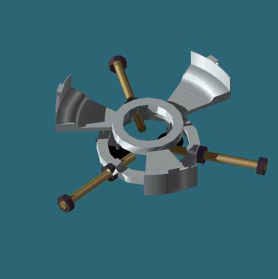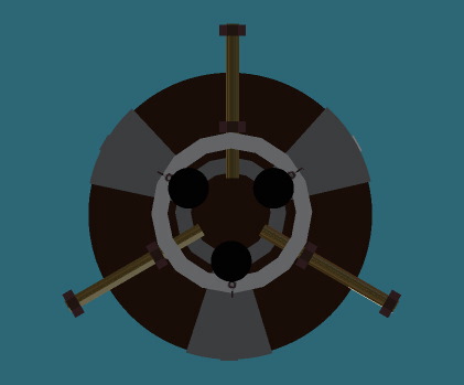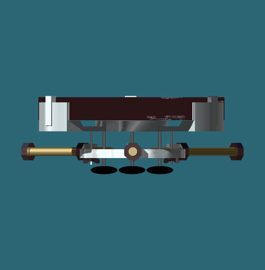
Above is a side view of the
mirror mounted in the cell. Visible underneath are the three screws
with wing nuts that adjust the mirrors angle. Once the desired adjustment
is made, the three black knobs are tightened to lock it in place.
These should be blackened with paint or tape to eliminate unwanted
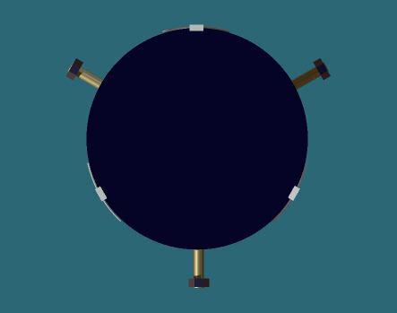
reflection (defraction). Extending from the sides forming a "Y" are three threaded rods. Each rod extends through the wall of the tube and is secured by a nut on the outside.