Updated January 4, 2004
| LANDING GEAR Updated January 4, 2004 |
||||||||||||||||||||||||
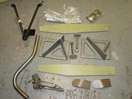
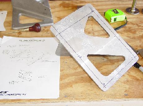
| Since I am a low-time pilot, I decided to replace the existing tailwheel set-up with the Diehl Tri-Gear Kit. Here is what I received. There were three kits: 1) the main gear, 2) the main gear axels (center), and 3) nose gear kit. The picture on the right shows the legs rounded off and ready to glass. | ||||||||||||||||||||||||
|
||||||||||||||||||||||||
|
||||||||||||||||||||||||
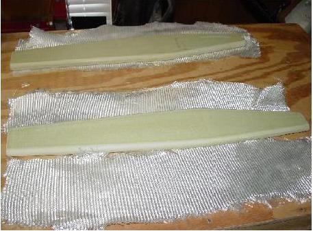
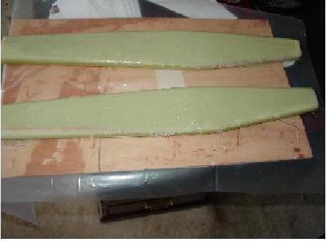
| Below left shows one edge of the gear leg laminated (cured). Right shows the remaining edge being laminatet with a layer of peel ply over the layup. The straws were floxed in next with two layers of BID Tape (not shown). | ||||||||||||||||||||||||
|
|
|||||||||||||||||||||||
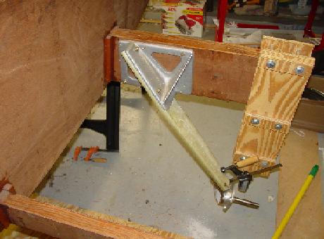
| I received in the Diehl kit a hand drawn drill template and the engineering drawings from RR. Unfortunately, when overlayed, they do not line up. I went with the engineering drawings and you can see my layout below left. After drilling the holes, The bracket was bolted to the spar and the gear leg attached. The leg will be floxed in later. I will remove the leg when shaping the underside of the stub wing. | ||||||||||||||||||||||||
|
||||||||||||||||||||||||
|
||||||||||||||||||||||||
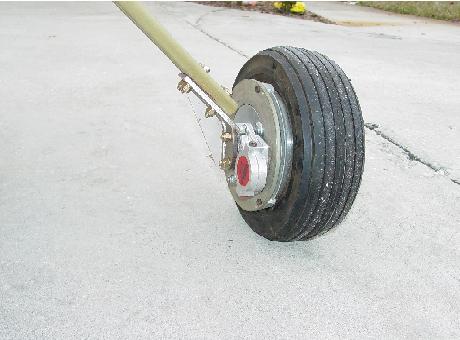
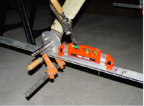
| I copied Mark Langford's idea of using the laser level to align the main wheels. The lower gear brackets are pre-bent at an angle to provide some degree of alignment out of the box. This allowed me to drill one hole to mount the lower bracket and then simply pivot it on that bolt to get the correct angle parallel to the main spar. The right picture shows the complete leg (from the rear). More can be seen on my Wheels & Brakes page. | ||||||||||||||||||||||||
|
||||||||||||||||||||||||
|
||||||||||||||||||||||||
| Next >> | ||||||||||||||||||||||||
| Return to Dean Cooper's KR2 Home | ||||||||||||||||||||||||