This is the major feature of Tesla's device: it operates differently to bladed units. Conventional centrifugal pumps and reaction turbines are most efficient at moderate pressure changes and high flowrates. Tesla's device works most efficiently at very low flowrates and high pressure changes - hence the absolute necessity for low-friction pressure seals on the rotor's inlet.
The disc turbine has some strong advantages. It is inherently well-balanced. The turbine is largely immune to the surge problem which limits centrifugal pumps. It has the potential to work quietly with air and to handle highly viscid fluids.
I tried building a device in the metal using this idea:
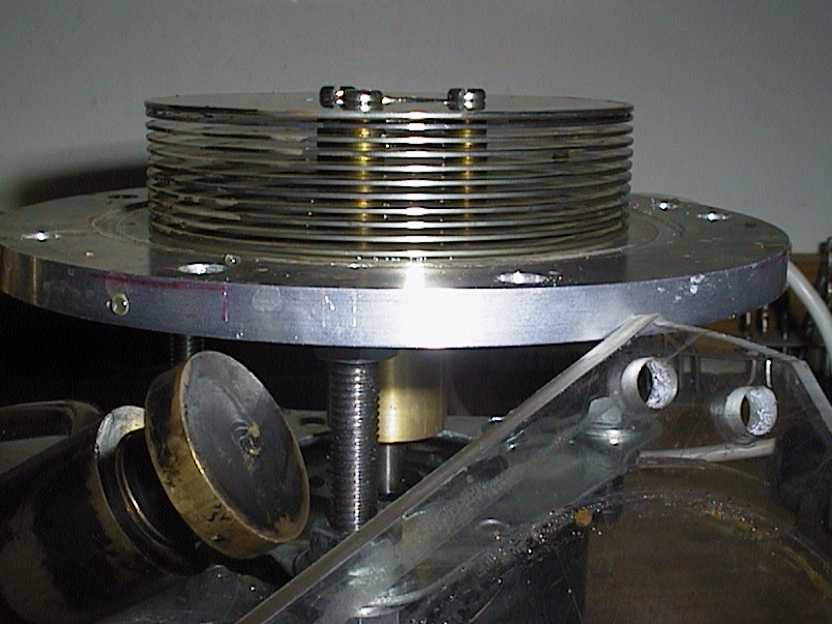
It did serve to show the validity of the idea. It also served to show that some very competent machining is needed to produce a decent efficiency device, and that the turbine has a high rotational inertia unless made of very thin discs.
The discs used here were out of a computer hard drive and made ideal blanks. The rotor stack is hollow-cored - I used three M3 screws to secure the stack to the face of the bearing shaft.
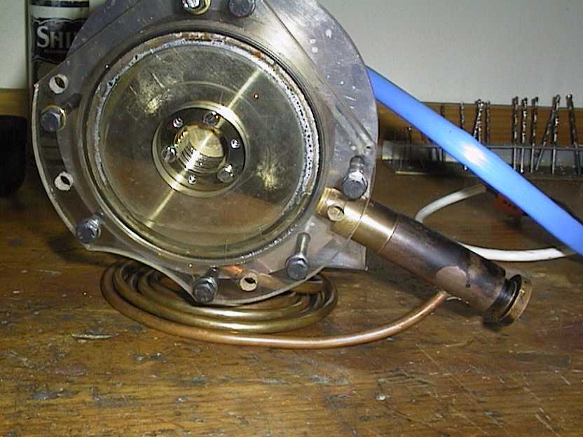
Before I'd attempted this device, I had made a semi-successful water pump, shown below:
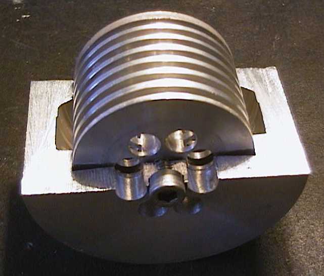
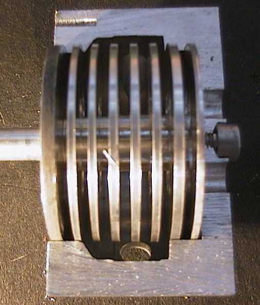
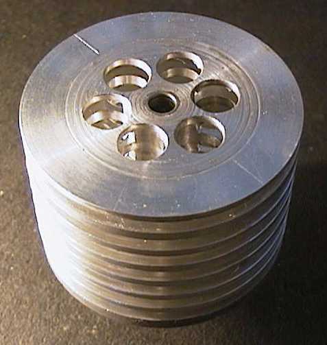
It did work, however. The impellor was made out of a solid bar, machined in a lathe by using a cut-off tool for the gaps between the discs. Ports were drilled afterwards. The device has four working discs and two sealing discs at each end.
The inlet shock loss mentioned earlier would also have been an issue, since the flow was asked to turn 90 degrees over the sharp edges drilled into the discs. You can see how the impellor would also 'chop' the flow from the housing inlets. Outlet flow was extremely smooth.
Tesla's device has some basic advantages as well as some basic problems. Bladed units seemed to complement these abilities and disadvantages. I thought that there might be a way to get the best of both worlds.