LED Patterns with AVR micro | ||||||||
| <<< Home | Disclaimer | Glossary | Strategy | Hardware Theory | Software Theory | Data | Questions | Links >>> |
|---|---|---|---|---|---|---|---|---|
| Introduction: New to AVR programming? This tutorial will help you get started on your first AVR 2313 program. | ||||||||
| Abstract | <<< Back |
|
This AVR Startup Project will create a rolling display pattern using up to 8 Light Emiting Diodes. But more importantly, this page demonstrates how to set up and run a basic program using the power ATMEL AVR development kit. It was one of my very first AVR programs, and one might say it is the hardware world's equavalent of the "Hello world" program. This guide will explain the AVR instruction on a line-by-line basis for the best clarity. |
| Disclaimer | ||||
|
ALL INFORMATION WITHIN THIS DOCUMENT IS PROVIDED "AS IS" AND WITHOUT ANY EXPRESS OR IMPLIED WARRANTIES, INCLUDING, WITHOUT LIMITATION, THE IMPLIED WARRANTIES OF MERCHANTIBILITY AND FITNESS FOR A PARTICULAR PURPOSE. I DO NOT GUARANTEE ANY INFORMATION IN THIS DOCUMENT IS ACCURATE, AND IT SHOULD BE USED FOR ABSTRACT EDUCATIONAL PURPOSES ONLY. THIS SOFTWARE AND DOCUMENTATION IS FREE OF CHARGE. COPYRIGHT (C) 2005 BY BRADY MAYES. ALL RIGHTS RESERVED. REDISTRIBUTION AND USE IN SOURCE AND BINARY FORMS, WITH OR WITHOUT MODIFICATION, ARE PERMITTED PROVIDED THAT THE FOLLOWING CONDITIONS ARE MET: 1. REDISTRIBUTIONS OF SOURCE CODE MUST RETAIN THE ABOVE COPYRIGHT NOTICE, THIS LIST OF CONDITIONS AND THE FOLLOWING DISCLAIMER. 2. REDISTRIBUTIONS IN BINARY FORM MUST REPRODUCE THE ABOVE COPYRIGHT NOTICE, THIS LIST OF CONDITIONS AND THE FOLLOWING DISCLAIMER IN THE DOCUMENTATION AND/OR OTHER MATERIALS PROVIDED WITH THE DISTRIBUTION. 3. ALL ADVERTISING MATERIALS MENTIONING FEATURES OR USE OF THIS SOFTWARE MUST DISPLAY THE FOLLOWING ACKNOWLEDGEMENT: THIS PRODUCT INCLUDES SOFTWARE DEVELOPED BY B.MAYES AND ITS CONTRIBUTORS. THIS SOFTWARE IS PROVIDED BY B.MAYES AND CONTRIBUTORS ``AS IS'' AND ANY EXPRESS OR IMPLIED WARRANTIES, INCLUDING, BUT NOT LIMITED TO, THE IMPLIED WARRANTIES OF MERCHANTABILITY AND FITNESS FOR A PARTICULAR PURPOSE ARE DISCLAIMED. IN NO EVENT SHALL B.MAYES OR CONTRIBUTORS BE LIABLE FOR ANY DIRECT, INDIRECT, INCIDENTAL, SPECIAL, EXEMPLARY, OR CONSEQUENTIAL DAMAGES (INCLUDING, BUT NOT LIMITED TO, PROCUREMENT OF SUBSTITUTE GOODS OR SERVICES; LOSS OF USE, DATA, OR PROFITS; OR BUSINESS INTERRUPTION) HOWEVER CAUSED AND ON ANY THEORY OF LIABILITY, WHETHER IN CONTRACT, STRICT LIABILITY, OR TORT (INCLUDING NEGLIGENCE OR OTHERWISE) ARISING IN ANY WAY OUT OF THE USE OF THIS SOFTWARE, EVEN IF ADVISED OF THE POSSIBILITY OF SUCH DAMAGE. THIS FILE IS DISTRIBUTED IN THE HOPE THAT IT WILL BE USEFUL, BUT WITHOUT ANY WARRANTY; WITHOUT EVEN THE IMPLIED WARRANTY OF MERCHANTABILITY OR FITNESS FOR A PARTICULAR PURPOSE.
|
| Glossary |
|
There aren't too many technical terms to work with here, but the are alot of hardware and software systems we need to get familiar with before we begin. AVR - This is the microcontroller we will be working with. The "AVR" comes from one of initials of one of the program's lead engineers. There are many popular AVR models on the open market; from the small 8-pin "ATTiny11," to the 40-pin powerhouses like ATmega8535. But the AVR 2313 seems to be a "standard issue" AVR for hobbists like myself. It's robust, versitile, and over all--low cost. Very recently, the AVR 2313 has been replaced with the even more-powerful Tiny2313 which is also compatible with the software below. STK500 Board - this is the circuit board that sends program code to the AVR. It features a serial data link to the PC, Six IC sockets for various AVR types, plus several buttons and LEDs for experimentation purposes. Details on this device may be found on the official ATMEL microntroller page. Decimal - our normal counting system. We notate decimal values by affixing a "d" at the end of our number (example: "255d"), or by writing the number normally (ergo: "255" has the same meaning as "255d"). Binary - digital numbering system. Notate binary by affixing a "0b" ("zero, b"-- not the letter O) in front of your value. Example: "0b11111111" is "255." Generally, use binary notation when using flags, bit operations or LCD pixel graphics. Hexidecimal - another digital numbering system. Notate hexidecimal values by affixing a "0x" in front of your value. (example: "0xFF" is "255" and binary's "0b11111111"). Generally, hexidecimal will be used with addressing. Why use such a strange numbering system? (1) Because it uses fewer characters than decimal or binary. And (2) it is easy to convert it to and from binary. Title Block - this goes at the start of most programs and shows you information like: program name, author, dates, emails, program descriptions, errata, and revisions. Title blocks are optional, but personally I think it is professionally derelict to leave them out. Click here to this website's standard title block. IDE - an acronym for "Intergrated Devolpement Environment" --and in this case--will refer to the programming environment that the AVR program will be created in. The additionally features such as the emulator, and diagnostics tools make this an "integrated" environment. ESD Shock - "Electro-Static Discharge" shocks are the result of the buildup of static charges on the human body. Touching an electronic device without proper grounding will deliver this shock to the device in most conditions. This charge can be associated with voltages thousands or tens of thousands of Volts strong, and can have a devestating effect on both the STK board and the AVR. It is important to ground yourself when working with either device to prevent damage to the equipment. |
| Design Strategy |
Design ConceptThis is a relativly straightforward project, so this section will not get bogged down in technical details. To skip to the software section, click here. First, we will create a simple assembly program inside the AVR studio IDE. Second, we will upload the program to the microcontroller itself using the STK500 support software. Finally, we will perform a "mock inspection" by downloading our own program from the chip and reading it in the IDE. |
| Hardware Theory | |||||||||||||||||||||||||||||||||||||||||||||||||||||||||||||
Electrical DesignIt is not required, but this schematic shows the type of circuit this program was meant for. Since the STK500 is an equivalent circuit, you may wish to skip this Hardware Theory section and jump straight into the programming
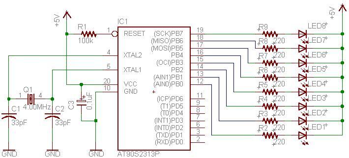
[ Click for larger image ] Schematic CommentsThe following schematic was intented for the AT90S2313-10PC or AT90S2313-4PC controller. In theory, it is compatible with the newer AT_Tiny2313 chip, but this compatibility has not been verified by myself. Bill of Materials
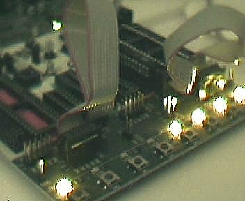
Part RequirementsMicrocontrollerThis schematic was designed with the AT90S2313 in mind. This chip has recently been replaced with the AT_Tiny2313, which is software-compatible, however this chip was not tested with this schematic. The unused Port D pins are held near the +5V supply voltage internally by the controller software. CrystalThe 4MHz crystal, Q1 is not a critical value and can range from 1MHz to 10MHz with the AT90S2313-10PC chip, or be as high as 20MHz with the AT_Tiny2313 chip. Discrete ComponentsCapacitors C1 and C2 where monolithic, however other types such as ceramics may be used. Capacitor C3 was aluminum electrolytic. All resistors featured had a maximum dissipation of 1/4 watt, however 1/8 watts versions are applicable too. The LEDs were provided by a bar graph display, however true discrete LEDs are just as useful. EngineeringRather than focus on the hardware, this page is meant to highlight the source code behind this project. To skip to the software section, click here. ConstructionThe main thing to keep in mind while building this circuit is to avoid damaging the STK board or the microntroller with a static shock. Proper grounding the only guarantee against this posibility. A plastic or rubber-lined IC removal tool will aid in removing the chip without bending any of the 20 interface leads. | |||||||||||||||||||||||||||||||||||||||||||||||||||||||||||||
| Software Theory | ||||||||||||||||||||||||||||||||||||||||||||||||||||||
Software LayoutThe source file featured on this page was tested and uploaded using ATMEL AVR Studio 4.
Software DesignWhat it all meansNow, this brief tutorial is going to step through the program one instruction at a time and explain it's meaning in better details. For further details I highly recommend downloading the AVR 2313 the pdf files at the official ATMEL website. The Program: HeadingsThis is the code listed after the large title block. At the start of each AVR program, it is important to make a few basic declarations before we begin to add our operating code. This step occours between the large commented title block and the line "rjmp main".
The Program: SetupMoving on, we'll meet the heart of the program. Unlike the program headers section, this segment will contain actual CPU instructions which will be loaded and executed by the microcontroller--whereas the headers are useful only to the compiler. Before we can get started, we'll have to setup a few ports and registers in the processor.
The Program: Main LoopNow that we've set the stage, things can really get interesting. This main loop will create the rolling display pattern.
| ||||||||||||||||||||||||||||||||||||||||||||||||||||||
| Data |
SummaryAnd this concludes the AVR programming tutorial. For further questions on the instruction set, please refer to the def2313.inc file distributed by the ATMEL Corporation, or view the featured source program [above] for more code commenting. |
| Questions |
|
Here are some questions I've seen regarding this subject. Q: I'm getting compile errors, what do they mean? Unknown Instruction Opcode - you entered a command the microcontroller will not recognise. This can happen if you mistype an instruction or if you try an instruction that is not supported by this AVR model. For example, the ATmega8535 supports the "MUL" command while the ATTiny11 does not. Refer to your device's data sheets for complete instruction listings. Unidentified Variable Referenced - you entered a register, constant, or program lable that has not been defined. This is most likely the result of misspelling. If you must define a new register or constant define them using the ".equ" and ".def" directives. Duplicate Lable - you are trying to give two program lables the same name. Correct this by removing or renaming at least one of the conflicting lables. The compiler will direct you to the last (furthest down) conflicting lable. Unknown Pseudo-Opcode - you tried to use a pseudo-command that does not exist. Pseudo-Opcodes are indicated by the "." in front of the instruction--as in: ".cseg" ".include" or ".org" Q: What's the difference between an error and a warning? Q: How did you get the programming board? Q: How long does it take to upload a program? |