TI Power Expander | ||||||
| <<< Home | Disclaimer | Hardware Theory | Software Theory | Data | Questions | Links >>> |
|---|---|---|---|---|---|---|
| Abstract | <<< Back |
|
The TI External Expansion Device I project will augment most TI graphing calculator's power supply. The system can drive the machine for up to 24 hours and a wall adapter support feature will eliminate the need for batteries alltogether. The system does this by taking advantage of the idea of stacking power sources in parallel and isolating them through basic components. Switching will be provided automatically with no programming required! |
| Disclaimer |
|
ALL INFORMATION WITHIN THIS DOCUMENT IS PROVIDED "AS IS" AND WITHOUT ANY EXPRESS OR IMPLIED WARRANTIES, INCLUDING, WITHOUT LIMITATION, THE IMPLIED WARRANTIES OF MERCHANTIBILITY AND FITNESS FOR A PARTICULAR PURPOSE. I DO NOT GUARANTEE ANY INFORMATION IN THIS DOCUMENT IS ACCURATE, AND IT SHOULD BE USED FOR ABSTRACT EDUCATIONAL PURPOSES ONLY. THIS SOFTWARE AND DOCUMENTATION IS FREE OF CHARGE. COPYRIGHT (C) 2005 BY BRADY MAYES. ALL RIGHTS RESERVED. REDISTRIBUTION AND USE IN SOURCE AND BINARY FORMS, WITH OR WITHOUT MODIFICATION, ARE PERMITTED PROVIDED THAT THE FOLLOWING CONDITIONS ARE MET: 1. REDISTRIBUTIONS OF SOURCE CODE MUST RETAIN THE ABOVE COPYRIGHT NOTICE, THIS LIST OF CONDITIONS AND THE FOLLOWING DISCLAIMER. 2. REDISTRIBUTIONS IN BINARY FORM MUST REPRODUCE THE ABOVE COPYRIGHT NOTICE, THIS LIST OF CONDITIONS AND THE FOLLOWING DISCLAIMER IN THE DOCUMENTATION AND/OR OTHER MATERIALS PROVIDED WITH THE DISTRIBUTION. 3. ALL ADVERTISING MATERIALS MENTIONING FEATURES OR USE OF THIS SOFTWARE MUST DISPLAY THE FOLLOWING ACKNOWLEDGEMENT: THIS PRODUCT INCLUDES SOFTWARE DEVELOPED BY B.MAYES AND ITS CONTRIBUTORS. THIS SOFTWARE IS PROVIDED BY B.MAYES AND CONTRIBUTORS ``AS IS'' AND ANY EXPRESS OR IMPLIED WARRANTIES, INCLUDING, BUT NOT LIMITED TO, THE IMPLIED WARRANTIES OF MERCHANTABILITY AND FITNESS FOR A PARTICULAR PURPOSE ARE DISCLAIMED. IN NO EVENT SHALL B.MAYES OR CONTRIBUTORS BE LIABLE FOR ANY DIRECT, INDIRECT, INCIDENTAL, SPECIAL, EXEMPLARY, OR CONSEQUENTIAL DAMAGES (INCLUDING, BUT NOT LIMITED TO, PROCUREMENT OF SUBSTITUTE GOODS OR SERVICES; LOSS OF USE, DATA, OR PROFITS; OR BUSINESS INTERRUPTION) HOWEVER CAUSED AND ON ANY THEORY OF LIABILITY, WHETHER IN CONTRACT, STRICT LIABILITY, OR TORT (INCLUDING NEGLIGENCE OR OTHERWISE) ARISING IN ANY WAY OUT OF THE USE OF THIS SOFTWARE, EVEN IF ADVISED OF THE POSSIBILITY OF SUCH DAMAGE. THIS FILE IS DISTRIBUTED IN THE HOPE THAT IT WILL BE USEFUL, BUT WITHOUT ANY WARRANTY; WITHOUT EVEN THE IMPLIED WARRANTY OF MERCHANTABILITY OR FITNESS FOR A PARTICULAR PURPOSE. |
| Hardware Theory | ||||||||||||||||||||||||||||||||||||||||||||||||||||||||||||||||||||||||||||||||||||||||||||||||||||||||
Electrical DesignFirst, I should note that opening any TI calculator automatically voids the manufacturer warranty on your calculator. This even applies to brand-new machines, so if you decide to proceed know that you do so at your own risk.
[ Click for larger image ] Schematic CommentsA few unusual parts to note here: components labled "JP2," "JP3," and "JP4" represent wire connections to outside devices. That is to say they represent the locations where the wires meet the circuitboard. The stereo jacks X1 and X2 show five pins instead of the expected three. Simply ignore pins "3" and "4" on both jacks. For optimal performance, the 100uF capacitor "C3" should be placed as close to the leads entering the calculator as possible. 100uF is the minimum suggested value. Bill of Materials
Part RequirementsIf you can't get the exact parts listed above, you can substitute them for similar ones. This section explains some of the substitution guidelines. Voltage Regulator RecommendationsThe 7806 regulator featured on this page can be replaced by most other +6 Volt regulators. For example, the first EED design used a NTE 962 Regulator; and the upcoming EED2 will use a much-smaller 78L06. The replacement must be able to conduct at least 50mA of constant current and it must be able to absorb at least 125mW of power. A heatsink can also help prevent any over-heating. The regulator's dropout voltage is critical. It will determine what type of wall adapter voltage can be used. Use the following expression as a guide. ...typical dropouts are between 1 and 2 Volts, so generally we assue the 6 Volt regulator will need a supply of 8 or more Volts. RelayNaturally, the new relay must be able to fit inside the enclosure--so "reed" and "sub-miniature" relays are preferred It should have a 4.5 to 6 Volt switching voltage and it needs at least one Normally-Open pin, one Normally-Closed pin, and one "common" pin. The coil resistance should be below 100 ohms. Isolation Diodes D1 and D2The two Schottky diodes (1N5817) are used to isolate the batteries from each other and prevent them from accepting each other's current. If Schottky diodes are not available to you, "general-purpose" diodes may be used instead, however this will decrease top battery life from 24 hours to 20 hours or even less. Clamping Diode D4This may be replaced by almost any general-use rectifier diode. The diode must have a reverse voltage rating of 10 volts or greater. It must have a forward voltage rating of 60 volts or greater. It should have a forward surge current rating of at least 1A. CapacitorsCapacitors C1, C2, and C3 are used as bypass capacitors. They are highly recommended, but not critical. This webpage features "monolithic"-type capacitors, but other types such as ceramic capacitors are useful. Capacitor C3 should be at least 100uF, and preferably larger if it can fit inside the casing. Stereo PortsThe 3.5mm supply power is totally optional. Its job is to provide 6 volts to future peripheral devices. If you don't plan to build an peripherals for the EED, you may leave it out all together. The 2.5mm link port is used for calculator linking (to replace the existing link port). Do not use "Mono" ports. Wall AdapterThe adapter featured on this webpage came from a cordless phone charger. Because of the 7806 regulator, the Expander can use power from almost any American standard wall adapter with a 2-terminal output plug, as long as it has the following properties:
Do Not plug the EED directly into a wall socket! Make sure the female power port matches the size of your adapter's male output plug. Also, parts may be substituted for international use, as long as the AC signal is clean. LED and ResistorBoth are truely optional. However if the LED is used, it needs the resistor to accompany it and limit the current the LED will pass. If you must substitute the resistor, use a value between 200 and 300 Ohms. The LED color is non-essential. #4-40 Thread screws and nutsThe #4-40 thread screws were selected for their small size. They may be substituted by #6-32 screws which are heavier and wider. Nylon or plastic screws are preferred over metal because they diminish the chance of corrosion. ConstructionCalculator PreparationWith all components and supplies handy, begin by removing all five batteries from the calculator. This includes the 3 Volt button cell locked in behind the metal lever. Store all removed screws and other parts in a separate place for safe keeping. Also, remove the slide case and set it aside. Now the case has to be unscrewed. I should reiterate that this will void any active warranty the calculator if it is new, so proceed at your own risk. Place the calculator face-down. At least 2 screw ports containing 2 black Phillips screws should be visible. Remove the screws and place them in a labeled container. The case is now unlocked, however it will still take a bit of prying to put the top and bottom casings apart. Gently pry--don't break--apart the casing. A broad, flat metal screwdriver, may be used to pry apart the cracks along the sides of the plastic casing. This should be a slow and deliberate effort, otherwise the casing will experience heavy scratching. You'll know the case has been separated by the "pop" of the snap in joints disconnecting. At this point, it is recomended that you ground yourself if possible. With the casing halves seperated, keep the circuitboard half and place the lighter half aside. Face the circuitboard half face down on the table so the anti-static foil if facing up and the LCD is facing down away from you. Removing the Positive Battery TerminalIn order to switch between power supplies you'll need to detach the existing positive battery terminal. Start buy cutting off the metal contact that is supposed to touch the (+)side of the battery. This metal is particularly tough to cut, and can absolutely ruin most good wire cutters. Dig out your rustiest, nastiest pair of nippers and clip away. Cut the metal contact down to its soldering, leaving the blob of solder intact. Keep the old metal contact in a separate container you'll use it again later. Leave the negative terminal alone. [Optional] Removing the Link PortUsing the desoldering equipment, carefully remove the calculator's small 2.5mm port from the circuitboard. The port is a surface-mounted device that makes 3 contacts with the systemboard (tip, ring, and ground). Keep desoldering by heating those solder joints while lifting the 2.5mm port out of the systemboard. When you're done, you'll leave behind 3 very, very small copper contacts. Quickly clean them off with rubbing alcohol. Drilling the Calculator CaseBefore anything can be attached, holes need to be drilled into the main casing and the battery casing. NOTE: strong adhesives may be used rather than drilling. Ten holes will be created in total: 3 in the back of the calculator casing, a matching 3 in the VELLEMAN casing; plus 2 in the battery casing, and a matching 2 in the external battery pack casing. Use this image as a general guide: Case Drilling Points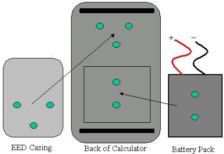
Drilling and Screw Locations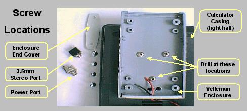
Drilling the Battery CaseDepending on the AA battery pack you have, you may have to also drill out parts of its interior in order the make room for the screws. The battery pack used in this guide came from Radio Shack, and it had 3 plastic "walls" inside that were meant to separate the four AA batteries. These walls had to cut out to allow a space for the #4-40 thread nuts. If the large #6-32 screw type is being used, take care that the screws will not block the AA batteries. If any of the screws or nuts are too long or too wide, they will have to be sanded down or replaced with a smaller counterpart. With all hole locations in place the attached devices should roughly resemble the image below. 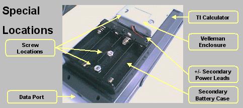
[ The Mark II Expansion Device ] The Power Switching CircuitThe Expander's schematic is pretty self-expanatory. Still, it may be beneficial to purchase a preforated board that has a pre-drawn traces on it. The component positioning is not critical, and there are a few pitfalls that can be avoided. The biggest problem is the small space allowed. Begin by placing the largest components near the center of the board, where they will have to most vertical clearance. The large stereo ports may have to be sanded down to allow enough clearance in the front of the gray enclosure. 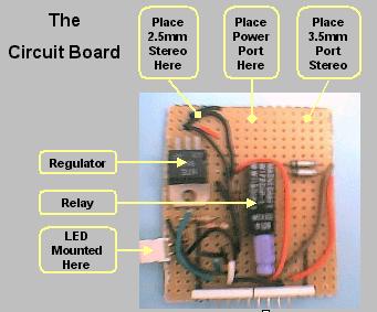
...keeping in mind, of course that the LED and 3.5mm port hookups are totally optional. | ||||||||||||||||||||||||||||||||||||||||||||||||||||||||||||||||||||||||||||||||||||||||||||||||||||||||
| Software Theory |
Device SoftwareThe Expander's switching ability is essentially "hardwired" with no dependence on software. The software section of this guide is intentionally left empty. |
| Data |
Project's Development ReviewIt is helpful to test the power switching circuit with a volt meter before connecting it to any of the calculator's circuitry. This generally speeds up construction and isolates any problems that may be caused by loose solder. Project's Operation Review1000-hour Test: ResultsI operated the EED in external mode for a total 42 calander days without incident. At the end of the 42nd day, the device was powered up and checked excessive heat, corrosion, and voltage drift. Following the inspection, the system was able to sustain peak power absorption (125mW) without incident or overheating. The Life Cycle test was performed in an indoor environment with an average ambient temperature of 73 degrees F. A regulator test was attempted by removing the auxilary power line while batteries were present. The result of this was the calculator auto-resetting due to the resulting voltage spike. Therefore, it should be noted to never unplug the EED without first turning off the calculator. This will cause the calculator to reset and lose all data. Likewise, the calculator must be turned off before plugging the EED in, or before installing new batteries. SummaryIn general, the project worked, but looking at things over the past year, there are few limits I would like to resolve. First, the main limitation here was the inability to switch power sources while the calculator was running. In the future, I would like to eliminate the relay entirely through the use of additional voltage regulation. The current system also requires the power adapter have a center-positive or center-negative output--it can accept one but not both. A full-wave-bridge in front of the fuse (F1) would eliminate that restriction. |
| Questions |
|
Here are some questions I've seen regarding this subject. Q: I live in a remote area. How can I order parts? Q: Does it recharge the batteries? Q: How long can I leave the EED plugged into the wall? Q: Do I really have to drill? Q: Why do I need the diode, D1. Q: What about power outages? Q: Earlier you said this could improve calculation times. Is this
overclocking? Q: If the Expander uses 8 batteries instead of 4, wouldn't the battery
life double instead of tripling? |