ISO Card Reader | ||||||||
| <<< Home | Disclaimer | Glossary | Strategy | Hardware Theory | Software Theory | Data | Questions | Links >>> |
|---|---|---|---|---|---|---|---|---|
| Introduction: The Card Reader project uses a small number of components to read many magnetic card types. | ||||||||
| Abstract | <<< Back |
|
The Magstripe (Track 2) Reader project can be used to view numerics stored a magnetic data card. Although there is no writeback ability, the device is very useful as a card debugger. The treatise will use an LCD character display to relay this data to the user. The circuit uses an AVR microcontroller and can modified to work with similar RISC controllers. |
| Disclaimer | ||||||
|
ALL INFORMATION WITHIN THIS DOCUMENT IS PROVIDED "AS IS" AND WITHOUT ANY EXPRESS OR IMPLIED WARRANTIES, INCLUDING, WITHOUT LIMITATION, THE IMPLIED WARRANTIES OF MERCHANTIBILITY AND FITNESS FOR A PARTICULAR PURPOSE. I DO NOT GUARANTEE ANY INFORMATION IN THIS DOCUMENT IS ACCURATE, AND IT SHOULD BE USED FOR ABSTRACT EDUCATIONAL PURPOSES ONLY. THIS SOFTWARE AND DOCUMENTATION IS FREE OF CHARGE. COPYRIGHT (C) 2005 BY BRADY MAYES. ALL RIGHTS RESERVED. REDISTRIBUTION AND USE IN SOURCE AND BINARY FORMS, WITH OR WITHOUT MODIFICATION, ARE PERMITTED PROVIDED THAT THE FOLLOWING CONDITIONS ARE MET: 1. REDISTRIBUTIONS OF SOURCE CODE MUST RETAIN THE ABOVE COPYRIGHT NOTICE, THIS LIST OF CONDITIONS AND THE FOLLOWING DISCLAIMER. 2. REDISTRIBUTIONS IN BINARY FORM MUST REPRODUCE THE ABOVE COPYRIGHT NOTICE, THIS LIST OF CONDITIONS AND THE FOLLOWING DISCLAIMER IN THE DOCUMENTATION AND/OR OTHER MATERIALS PROVIDED WITH THE DISTRIBUTION. 3. ALL ADVERTISING MATERIALS MENTIONING FEATURES OR USE OF THIS SOFTWARE MUST DISPLAY THE FOLLOWING ACKNOWLEDGEMENT: THIS PRODUCT INCLUDES SOFTWARE DEVELOPED BY B.MAYES AND ITS CONTRIBUTORS. THIS SOFTWARE IS PROVIDED BY B.MAYES AND CONTRIBUTORS ``AS IS'' AND ANY EXPRESS OR IMPLIED WARRANTIES, INCLUDING, BUT NOT LIMITED TO, THE IMPLIED WARRANTIES OF MERCHANTABILITY AND FITNESS FOR A PARTICULAR PURPOSE ARE DISCLAIMED. IN NO EVENT SHALL B.MAYES OR CONTRIBUTORS BE LIABLE FOR ANY DIRECT, INDIRECT, INCIDENTAL, SPECIAL, EXEMPLARY, OR CONSEQUENTIAL DAMAGES (INCLUDING, BUT NOT LIMITED TO, PROCUREMENT OF SUBSTITUTE GOODS OR SERVICES; LOSS OF USE, DATA, OR PROFITS; OR BUSINESS INTERRUPTION) HOWEVER CAUSED AND ON ANY THEORY OF LIABILITY, WHETHER IN CONTRACT, STRICT LIABILITY, OR TORT (INCLUDING NEGLIGENCE OR OTHERWISE) ARISING IN ANY WAY OUT OF THE USE OF THIS SOFTWARE, EVEN IF ADVISED OF THE POSSIBILITY OF SUCH DAMAGE. THIS FILE IS DISTRIBUTED IN THE HOPE THAT IT WILL BE USEFUL, BUT WITHOUT ANY WARRANTY; WITHOUT EVEN THE IMPLIED WARRANTY OF MERCHANTABILITY OR FITNESS FOR A PARTICULAR PURPOSE.
|
| Glossary |
|
BPI [Bits Per Inch] - A common measurement of card recording density. Breadboard - A slang term for a tool uses in circuit prototyping. The breadboard has a set of electrically connect grids that components and wires can be snapped into. It is a common alternative to soldering, which is a more permanent process. Dropout (Voltage) - An input-output voltage differential in which the regulator ceases to regulate properly if the input voltage is lowered any further. The dropout is the point where the output lowers 100mV or more due to the input's lowering. For example: if a 5 Volt regulator requires a 7 Volt input, the dropout is 2 Volts. Dropout voltages for general-purpose regulators typically range between 1 and 3 Volts. Edge-triggering - To trigger a software event only on a high -> low or low -> high transition of an input. Unlike level triggering, this prevent the software from over-sampling a signal, and allows for easier software control. HD 44780 - A widely used hardware/software standard for LCD character displays. All displays supporting HD44780 tend to have the same initialization, setup, and communication procedures. They support the ASCII character set. ISO, ISO 2 - A voluntary, non-treaty organization responsible for creating international standards in computers. ISO 2 will refer to the data track that will be checked by the reader. LCR [Longitudinal Redundancy Check] - A type of checksum that is based on the total number of 1's in a chain of binary numbers. An LRC will look at the total number of 1's in the least significant bit and generate a 1 if the total is odd, or 0 if the total was even. The process is repeated for the next significant bit and so on. Level-triggering - To trigger a software event based on a pin's "high" or "low" status. Magstripe - this is pet name for the type of card we will be working with. Unlike optical and smartcard devices, a classic magstripe can be identified by the dark band spanning the card's backside. Quiescent Current - The part of a regulator's input current that does not contribute to the output current. Recording Density - A measurement of how many bits can be stored in a linear inch on a magnetic card. The cards uses in this document were recorded at 75 Bits per inch. Sampling Theorem - This rule states that given a discrete signal, the rate of recording sampling must be more than twice the signal's maximum frequency in order to recreate it. The consequence of sampling lower than this rate is often ailiasing. TTL - Refers to the very-common standard of digital signaling in which a 5-Volt signal indicates a logic "High" and a signal of 0 Volts represents a "Low." The standard defines window of error for these voltages, as well as a noise margin in which the signal may become ambiguous. |
| Design Strategy |
Design Concept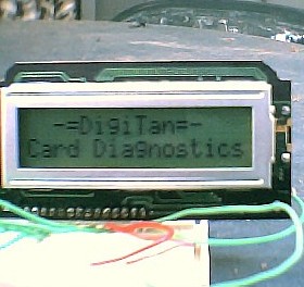
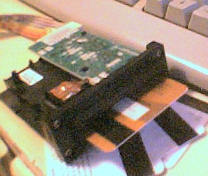
Unlike many projects that will succeed this one, the ISO Card Reader circuit will not have the normal project enclosure, so construction will not be on our list of topics. The purpose of this treatise is only to demonstrate a typical card-reading methods. The experimental reader circuit here was divided into three major components. They are, in no particular order:
All of these components were made from widely-available parts that can found at most online retailers, including the five listed on this site's weblinks page. A larger project would have been nice, but the goal behind this design was cost-effectiveness and ease-of-use. For a pin description of the Panasonic ZU-M2121S451 reader, continue to the Hardware Theory Section. The LCD character display shown in the above picture is also covered in the Hardware section. Project Sub-initiativesCard Format ResearchAfter trying some search engine research on the reader, I was discouraged in the lack of technical data on the web. Even Panasonic's own datasheets were vague; the data could easily pass as a brochure but not a technicial document. The only exception was one UC Berkley page written by Tobin Fricke involving a reader-to-PC gameport adapter, and hence the assembly program seen here was based on that information. In any case, the shortage of useful data was not critical. And luckily, the Panasonic ZU-system is equipped to "decipher" the magnetic flux changes that will represent any stored data. As such, this guide will save time and focus on clock-data synchronization and error detection. Otherwise, we would be stuck with the job of dealing with the "physical layer" of the card format. The FormatMagstripe cards store data on a broad, dark brown strip. This band is invisibly divided into three tracks that run "length-wise" across the stripe. In general, track 1 is a text track and holds names, street addresses, and similar information. Track 2 is optimized for numerics and holds account numbers, IDs, dates, etc. Track 3 is closest to the center of the card and holds discretionary data that varies from writer to writer. Tracks other than #2 won't be discussed, but for a little magstripe trivia: the card holds a total 1,288 bits between all three tracks. Not as much as most people expect. Track 2 numbers are coded in BCD so characters only need to have 4 bits to make each number distinguishable. Then, six markers make up the six remaining binary possibilities (values 10 through 15). Finally, a 5th parity bit is added. If the 4 BCD bits contain an odd number of 1's, the parity bit will be set to 1. In summary: Character length = 5 bits Card DetectionThe system can save power if it only attempts to read once a card is present and ready to be scanned. The reader used here offers a very simple interface that will signal when a card is inserted. Additionally, there are indicators for card motion, and the card end-stop (deepest insertion point). Error DetectionDuring the programming phases, I tried three versions of read error detection: The successful method was to run a parity check based on the 5th bit attached to every BCD/marker. In the event that a character is corrupted, the parity bit will have fair chance of detecting a problem. There are major limits. Parity bits will not be effective in some situations where errors occur in pairs. For example: "1111" "1100" "0011" and "0101" will all produce the same parity (in addition to four other combinations). It is easy to imagine how this can become a problem. ...The LRC checksum makes a good second option for this very reason. This is not a true checksum: the LRC is a parity check on the entire data sequence (except itself). It is a 4-bit parity word that is generated by checking bits by order of significance. In other words, bit 0 of the LRC is the parity of every bit 0 that occured in all 39 bytes before it. Bit 1 is the parity of every bit 1, and so on. Finally the 5th bit of the LRC is a parity on the LRC itself. The LRC will be the final character read in any insertion-reader. All parity bits used on the magstripe are odd-triggered. Finally, it is possible to exploit the fact that the card is filled with markers called "sentinels" that occur in predictable locations. "Predictable," that is--for most credit cards. Truthfully, ISO standards to not seem to reign over marker use, so this is generally the least-reliable method of finding a problem. But it does make logical sense to reject a scan reveals 100% markers, and 0% markers. The reader used here uses the first approach. Should an error appear somewhere on-screen, a red "error" LED will be activated to instruct the user to reinsert the card. Content DisplayThe digital contents of the card need to be displayed in a readable manner. This was a good opportunity to dust off one of the few 16x2 character displays that have lying around the lab area. In addition to showing the card contents, the data address can be printed to allow for more clarity. Scrolling keys were added to cycle through various addresses of the magstripe so that the entire track can be debugged. And with the basic design concept out of the way, we can move on to the hardware theory... |
| Hardware Theory | |||||||||||||||||||||||||||||||||||||||||||||||||||||||||||||||||||||||||||||||||||||||||||||||||||||||||||||||||||||||||||||||||||||||||||||||
Electrical DesignWith both the card reader and LCD device operating with the AVR's TTL signals, completing a prototype circuit was a bit trivial, so this section will focus mainly on component selection/substitution, and device behavior. The schematic for the latest version is also available.
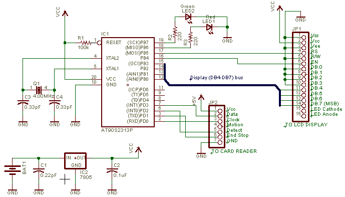
[ Click for print version ] Schematic CommentsAlthough they are not shown, 0.1uF capacitors will --if placed on the supply leads of the AVR, display and card reader-- marginally reduce any voltage transients caused by digital activity. Pin headers JP1 and JP2 represent the connections to the display and card reader. Both devices are explained in greater detail below... Bill of Materials
Part RequirementsCard Reader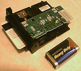
Many readers besides the Panasonic "ZU" series would have been acceptable. Whether you prefer an insertion reader or a swipe variety, important features to look for are the data and clock pins, because this will indicate that the magnetic signals have already been decoded. Some readers will have the option of card detect, card end stop, and card motion sensing. These features are useful in most situations, but are not required. I should also mention that the insertion reader was not able to scan the entire data track. Rather, the card would only pass about 3/4's of it's data to the read head before striking the end stop. This was unexpected and naturally caused a few software problems. If you are intent on reading LRC or any other data at the end of the card, it would be best to search for a swipe-reader. Continuing, the reader should be configured to ISO standards 7810 and/or 7811 to be useful in the U.S., and the F2F recording method should supported. The software attached here also assumes inverted output logic from the reader, and a card data density of 75 Bits Per Inch. The Panasonic model is applied in indoor office or residential settings. According to card datasheets, exposure to moisture or dust will cut the card's lifespan down as low as 1/5. Projects involving outdoor card scanning will justify a more rugged design that is more suited to damp or dirty environments. It is also a little-known fact that the cards should be kept dust-free in any way possible.
LCD Character DisplayThis treatise is not meant to explain the LCD display in much detail, but it does have a few basic requirements. First, the display used in this project used an HD44780-compatible controller. HD44780 is a very common display standard for these 16x2 readouts, and it dictates everything from initialization to the character set; ands it's tricky to find one in the U.S. that doesn't support the standard. The LCD shown on this page was not factory-designed to fit PCB boards, but rather had several right-angle connectors soldered directly to it's interface. This allowed me to fit the display onto the breadboard; like a giant Single In-line Chip. The display featured here is the Sharp LM16X21A, while a Lumex LCM-S01602DSR/A was used in the earliest prototype. Just like the card reader, many other types would have been acceptable. The pinout for the Sharp model was as follows:
Voltage RegulationVoltage regulation will be optional if the card reader will run off a reliable battery source. However, many battery combinations would still require a voltage divider of some sort to place the supply voltage within the 4.0 - 5.5 Volts the AVR, display, and card reader will tolerate. One possible substitutes for the standard LM7805 are: the LM2931 Low Dropout Regulator. The LM2936 Ultra-low Quiescent Current Regulator will also work, but it will not support the typical 160mA+ requirement for LCD backlighting--so use it for daytime-only applications. The LM2931's 100mA limit may also make backlighting difficult if much brightness is required. Connectors and SocketsThe Panasonic reader came with a 7-pin male locking socket with the 50 mil spacing that matches most breadboards. The connect it to the protoboard, I had to purchase 1 female and 1 male locking socket, plus cut 7 strands of hookup wire to work as an "extender." Pin 1 is indicated on the card reader's circuit board in white print. The card datasheet also suggests using cables no longer than 300mm (~1ft). EngineeringWith both the card reader and display providing rugged TTL interfaces, much of the hardware design was straightforward. In prototyping the main difficulty was in locating and building parts for the JP1 and JP2 interfaces that would connect the reader and display (respectively) to the breadboard. Card Reader Pre-InspectionBefore you begin constructing everything, it is prudent to pre-check the card reader so you are confident is it undamaged. A logic probe with TTL/CMOS capabilities will be necessary to perform a thorough test. First, try applying the 5 Volt supply to the Vcc and GND pins of the reader. If the pin numbering has been matched, the card reader will have a 5V voltage drop. Otherwise (if the pins were reversed), a short circuit will appear between the supply leads and the voltage drop will become 0. Next, the logic probe can be used to verify that each output is in the default "high" state. Inserting a compatible card should cause the outputs to change in various ways. Since none of this outputs can have the high-Z condition, the probe should either give a "high" or "low" at all times. Display Pre-InspectionTesting a display can be a difficult task especially if it is your first one. Luckily most HD44780 types have a built-in "pixel test" that will darken the entire top row on powerup. Apply 5 Volts to the Vdd and Vss pins, then look for this pattern. If nothing appears, chances are, your Vee (contrast) voltage is incorrect. The voltage should typically be a ground, but a few models require a 5 Volt level for the best contrast. At any time, you can verify that the display is receiving data by adding a routine to check the display's ready/busy status. This mode is not supported by either the schematic or the AVR program, but a display datasheet should explain exactly how to use this feature. The ready/busy reports will not only verify that the display is working, but will also allow the display routines to run faster than the ones featured on this page. | |||||||||||||||||||||||||||||||||||||||||||||||||||||||||||||||||||||||||||||||||||||||||||||||||||||||||||||||||||||||||||||||||||||||||||||||
| Software Theory | |||||||||||||||
Software LayoutHere is the assembly source code for the reader program. As usual, a detailed description of how the program works is featured below the title block, and nearly all instructions were commented. NOTE that if you plan to use the source or hexfile, you must also upload the .eep file to the AVR or else the LCD display will not work at all.
{"The source file was tested and uploaded using ATMEL AVR Studio 4."}
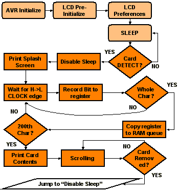
Software DesignLearning How to SampleThe challenge in receiving the card data will be edge-triggering the "read" routines. The falling edge of the clock signal is supposed to indicate that the AVR should sample the current data bit. Using the pinD shadow register in the SRAM, we can isolate the clock pin and sample it for a low level. Then one the data bit is collected by the program, we hold until the clock pin returns to its default "high" state. The purpose of this is to avoid the common mistake of level-triggering the read routine, which would allow 1 bit to be misread as many. Finding the Sample PeriodOne thing that may be problematic is finding the card data rate. Data arrival is always dependent on how fast the user wants to insert the card, so it is not reasonable to expect a fixed bit rate. However, once we know the recording density [Bit Per Inch] and the maximum allowable insertion speeds, we can determine a window for probable data rates. The data period or "spacing" (measured in seconds) is given by the relationship: Most read-only scanners will tolerate insertion speeds up to 60 cm/sec. It is rare to see a rating for minimum speed written in ink, however friction will impose a practical limit of about 4cm/sec. If we assume the fastest insertion speed will be 60 cm/sec and a density of 75 BPI, the above equation implies the max data period will be 564us, or 1,772 bps. To satisfy the sampling theorem, the program needs to sample faster than double this rate, otherwise aliasing my result. This imposes a minimum sample rate of 3,544Hz, with 282us or less between samples. Using similar logic, we can estimate that our 4 cm/sec minimum rate will imply a minimum data rate of 118 bps, with an 8.46ms data period. It may be prudent to treat any delay longer than 8.46ms as a "timeout" and tell the user to reinsert the card (and at a more reasonable pace). Serial killing: Bit ShiftingSerial data forms aren't very useful inside a microcontroller. To translate the incoming serial binary to the 40 (parallel) characters, we had to apply some bit shifting and rotation commands, namely: ror and lsr. If the card reader sent us a "0," we would set the carry flag using the sec command (we set instead of clear, because the reader outputs inverted logic). Next we shift that bit into a register using the ror command, which places our set carry flag in the bit7 position of the register and shifts all other bits right once. This was repeated for the remaining 4 bits of the incoming character. Finally, with all 5 character bits received and occupying the 5 highest bits of the register, we typed "lsr" three times to shift those bits to the 5 lowest bit positions. The whole process was repeated with the remaining 39 incoming characters. Displaying Data in Plain English"Plain English" may be a bit of an exaggeration, but a good interface will make the card contents somewhat more comprehensible. With only numbers and symbols to display, the visual interface does not have to be very complex. Any numerics on the card will be in BCD form, while six symbols (colon, semi-colon, left bracket, equal, right bracket, question mark) will represent start/end markers, dividers, and other sentinels. 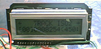
But since the screen can only accommodate 32 of the total 20 characters at once, the program will have to display an offset value so the user will always know what area of the card is under scrutiny. The program featured here had a default offset of 00 bytes with each card; and this number is indicated in square brackets. We included the words "Track ISO2" for clarity, and two scroll arrows were added to suggest how to use the left/right direction keys. Even with all this on such a small screen, there was room to display 12 BCD character. When the offset approached byte 38 (40 total bytes - 12 visible), the offset would auto-reset to 0x00. Detecting Read Errors: The LRCAs mentioned before, the LRC is a final check on the previous 39 characters. It is 1 byte in length --and visually--it makes the total number of 1's in a 'row' of bits even. For example, the LRC byte for the bytes 0001 0101 1111 00000 would be: "1011". First it takes the total number of 1's in each bit0 position and sets its 0th bit if the number is odd. This logic is repeated for the bit1-bit3 positions. The parity bits of the leading 39 characters are ignored. The 5th bit of the LRC is a parity check on the LRC itself. It follows the same logic as any other parity bit on a magstipe. In other words, it will be set if the LRC has an odd number of 1's. |
| Data |
Project's Development ReviewDisplay and EEPROM DifficultiesAt one point, the entire project was delayed for five hours due to perceived display failure. This was indicated by the entire display being filled with black rectangles instead of text characters and spaces. Since text was stored in the EEPROM part of the code, the EEPROM array was suspected. After invoking the STK500's EEPROM verify function, it was revealed that the blanking was caused by the EEPROM "erase device" option in AVR Studio 4. It became obvious that this function affected both AVR flash, and EEPROM memory--where text was stored. Although it was not included in this version, it may be prudent to include a software function that uses the LCD's busy/ready pin to verify that the display is responding. This would have eliminated much of the time wasted inspecting the display instead of the error's true source. Card Endstop ProblemsLate in the project, it was discovered that the endstop was physically preventing the card from being fully inserted, and only about 75% of data was able to be read. This also meant that the LRC checksum was always out-of-reach. For swipecard compatibility, the software above was still designed to read all 200 bits. However, if you plan to only use the Panasonic model featured here, you may want to program the AVR to stop collecting data as soon as the end stop is detected. Sleep Mode ProblemAfter activating processor sleep mode, the control program was not able to proceed even after the proper "wakeup" signals were applied to the detect and clock pins. Thus, sleep mode was removed from the program. I am looking into the cause of the problem. Project's Operation ReviewThe date, the E13 project has not been given a permanent enclosure, so the typical 1000-hour test has not been applied. In general, the project went well until it was discovered that a quarter of the card data was in accessible. This introduced a list of problems that could easily compromise the project's error-detection abilities. Card Format Research ReviewThere are a large number of good webpages that will explain the physical card format. However the data on the Panasonic ZU-M2121S451 reader was extremely poor in detail and quantity. Card Detection ReviewCard detection was successful. Card endstop detection is supported by the schematic, but was not used by the software. Error Detection ReviewSome card scans were successful with the above control program, however other cards appeared to be prone to errors. Often, sentinels were simply out-of-place. Other times, the red "parity error" LED would become active to indicate that there was an error on-screen. Unfortunantley, I was not able to determine the cause of these errors; but data bus noise and bus impedance are suspected. Also, I must reiterate that no official data has been published by the Panasonic company about this equipment, so it is impossible to know the exact behavior of the device without extensive testing. Content Display ReviewThe card content display code went very smoothly. Full left/right scrolling was possible using the direction keys, and there were no display problems to report. SummaryAlthough the project did not run smoothly in the end due to the endstop and parity errors, things were an overall success. If any additions are made to the system in the future, it is likely to apply a new reader that will allow the AVR to view then entire cardspace, including the LRC. |
| Questions |
|
Here are some questions I've seen regarding this subject. Q: Can the system do writeback? Q: What about international cards? Q: I can't find a card reader anywhere. Q: When I power up, nothing happens. Q: The debugger shows all zeros. Q: I need help for a project on card based unlocking systems. Q: Why does your reader keep reading after the card is fully inserted? Q: The debugger stops scrolling at byte "27" instead of "40." Q: Are there any more guides on card reading? |