Balloon Pump
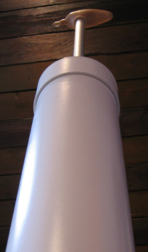
This is a picture of the pump to show you what it would look like to a six inch gnome. Pity the gnomes, their world is a scary place.
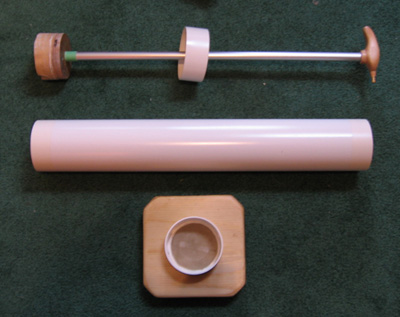
This is the pump disassembled. One of the things that the military taught me was that if you can't take something apart to fix it, you have to replace it when it breaks. That would be way to much effort. Unfortunately I couldn't come up with a easy way to make the handle removable, and still have a reliable seal, so both it and the piston are glued on and pinned with brass pins.
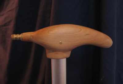
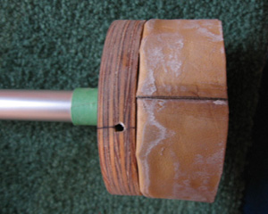
My favorite part of the pump. A brass hose barb in a 3/4 inch maple dowel in a one of a kind, hand crafted (by me) maple handle. Pinned onto the aluminum piston tube with more brass (I love brass). I originally intended for the hose barb to connect directly to the handle, but there were no suitably sized versions that could handle the whole range of balloon sizes, so I had to improvise.
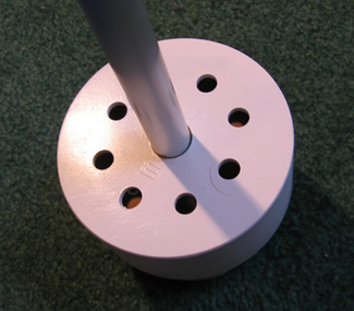
This is the cap for the tube of the pump. It's only real functional use is to keep the piston tube centered when the pump is used. Plus, as an added bonus when the pump is drawn upwards, the air escaping through the holes makes a rather distinctive hooting sound. Reminiscent of a slide whistle.
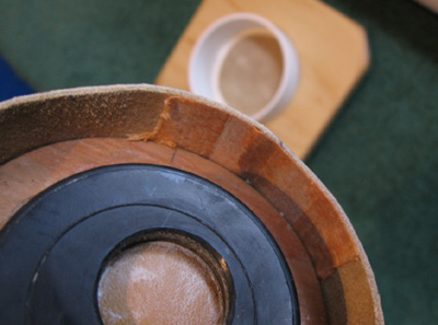
Side view of the working part of the pump. The piston tube is glued and pinned to the circle of plywood on the left, and the leather seal is attached to a second (smaller) circle which is hidden.
The seal works as follows: on the upward stroke, the leather doesn't seal all that well, which is fine, as the pump only work in one direction. On the downward stroke however, the elevated air pressure in the lower half of the pump forces the leather agaist the side of the cylinder wall, making the seal much more efficient.
This can actually be seen in the picture above, if you look at the whitish areas on the leather. This is residue from some white grease left over from an attempt to lubricate another failed piston design. There is a ring around the lower (right hand side in the picture) area on the leather. It forms a ring around the leather, except where the seam in the leather makes it too stiff to easily conform the the wall of the cylinder.
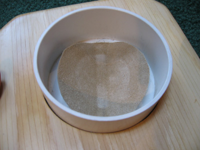
A look at the peice of random orange fabric that I used to reinforce the seam in the leather. I wish I knew more about leather work, since as I mentioned, this area is significantly stiffer than the rest of the leather, and lessens the quality of the seal. It also shows the valve which keeps a half inflated balloon from having the air sucked out of it if a second pump stroke is necessary.
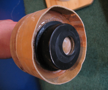
This is the full view of the piston valve, a one way check valve made from an abs pipe cap. There is a whole drilled off center and a leather flap glued to the other side. The flap is only glued down on one side, allowing the air to flow out to the balloon. Once the pressure of the air stops flowing from the piston into the balloon, and the balloon attempts to force the air back through into the piston, the leather flap is pushed down onto the hole, plugging it, and keeping the air where it should be.
When I first glued this valve on, I decided to check to see if it worked properly. I got a big lungful of air and blew heartily into the aluminum tube to see if any air would escape. Since the glue had not properly set, I managed to blow the whole valve right off. Oops.
The valve on the bottom of the pump is much the same as the smaller version on the piston. There are two half circle holes, with a strip running between them to which the leather is glued. Since this seal is much larger, the peices of plastic cut out of the holes were cleaned up and glued back onto the leather, to give them some rigidity, and keep them from being pushed all the way through the hole.
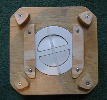
The base is elevated to allow air to pass freely into the valve. The bottom ABS cap is inserted into a hole cut through the plywood base, and kept from coming all the way through by two plywood shelves. You can clearly see the plastic peices on the valve flaps, and the plexiglass bar that is there to keep them from being blown out too far.
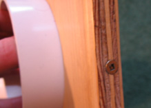
Two screws on opposite sides of the base are of an appropriate length to just prick the sides of the base cap to keep it from coming loose, but to allow it to be removed if there is ever a need.