| Home Glossary Colorbooks |
| Introduction | l | Formats | Features |
| l | l | Media | Models |
|
Audio Audio Compact Disc (CD) - Introduction The audio compact disc or CD is a media for storing digitally sampled audio. A CD audio disc holds approximately 74 minutes of stereo music recorded with 16-bit resolution -- and incorporates a number of error reduction, detection and correction techniques. The compact disc was launched in 1982. The first recording released on CD was Billy Joel's 52nd Street. The CD offered the home consumer for the first time, high quality digital audio in a robust and convenient format. The main attractions for the CD was the ability to play your favorite 'record' more than just a few times without leaving scratches, noise or damage, as the CD was very durable. The consumer also enjoyed instant access between tracks, the remote control facility and the small size. The disadvantages at launch was that few titles were available and the cost of the CD's was much higher than that of both vinyl and cassette tape. CD player prices were also much higher than turntables and cassette decks back in 1982. But the catalog of music through the 1980s quickly grew and player costs came down. By 1993 just 11 years after launch, the CD dominated the market in music sales. Technical information:
The CD disc is a 120 mm
(12 cm) diameter disc of mostly polycarbonate. The center contains a
hole 15 mm in diameter. The innermost part of the disc does not hold data. The
active data area starts at the 46 mm diameter location and ends at the 117 mm
diameter location. The 46-50 mm range is the lead in area and the 116-117 range
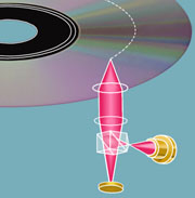
is the lead out area. The tracks are separated by approximately three times the wavelength of green light. Diffraction from these features (so very close to the wavelength of light) is what gives CD discs their beautiful colors. A thin layer (50-100 nm) of metal (aluminum, gold or silver) covers the pits. An additional thin layer (10-30 microns) of polymer covers the metal. Finally, a label is silk-screened on the top. Notice that the pits are far closer to the silk screened side of the disc (20 microns) than they are to the read-side of the disc (1.55 mm). Thus, it is easier to permanently damage a disc by scratching the top -- than the bottom! The fabrication of a CD: The process begins by making the "glass master". To do this, a glass plate about 300 mm in diameter is lapped flat and polished. The glass plate is coated on top with photoresist. A mastering tape is made containing the information to be written on the disc. A laser then writes the pattern from the master tape into the photoresist. The photoresist is developed. A layer of metal (typically silver over a nickel flash) is evaporated over the photoresist. The master is then checked for accuracy by playing the disc. The master is then subject to an electroforming process. In this electrochemical process, additional metal is deposited on the silver layer. When the metal is thick enough (typically a few mm's) the metal layer is separated from the glass master. This results in a metal negative impression of the disc -- called a father. The electroplating process is then repeated on the father. This typically generates 3-6 positive metal impressions from the father before the quality of the father degrades unacceptably. These impressions are called "mothers". The electroplating process is repeated again on the mothers. Each mother typically makes 3-6 negative metal impressions called sons or stampers. The sons are suitable as molds for injection molding. Polycarbonate is used to injection mold the CD discs. Once the discs are molded, a metal layer is used to coat the discs. Aluminum, gold, copper and silver are all reflective enough to be optically acceptable. Gold is typically too expensive and copper has a peculiar appearance. Thus, aluminum and silver are the most commonly used metals. Following metal deposition, a thin plastic layer (1-30 microns) is spin-coated on over the metal. This can be a nitrocellulose layer suitable for air drying, or an acrylic plastic that is cured in UV. Finally, the logo and other information is silk screened on the top. Reading the pits: The CD disc is actually read from the bottom. Thus, from the viewpoint of the laser beam reading the disc, the "pit" in the CD is actually a "bump". The polycarbonate itself is part of the optical system for reading the pits. The index of refraction of air is 1.0 while the index of refraction of the polycarbonate is 1.55. Laser light incident on the polycarbonate surface will be refracted at a greater angle into the surface. Thus, the original incident spot of around 800 microns (entering the polycarbonate) will be focused down to about 1.7 microns (at the metal surface). This is a major win, as it minimizes the effects of dust and scratches on the surface. The laser used for the CD player is typically an AlGaAs laser diode with a wavelength in air of 780 nm. (Near infrared -- your vision cuts out at about 720 nm). The wavelength inside the polycarbonate is a factor of n=1.55 smaller -- or about 500 nm. The pit/bump is carefully fabricated so that it is a quarter of a wavelength (notice a wavelength INSIDE the polycarbonate) high. The idea here is that light striking the land travels 1/4 + 1/4 = 1/2 of a wavelength further than light striking the top of the pit. The light reflected from the land is then delayed by 1/2 a wavelength -- and so is exactly out of phase with the light reflected from the pit. These two waves will interfere destructively -- so effectively no light has been reflected. The spacing between pits is equally carefully selected. Recall from basic optics that the image of a beam passing through a round aperture will form a characteristic pattern called an Airy disc. The FWHM (full-width half-maximum) center of the Airy disc pattern is a spot about 1.7 um wide and falls neatly on top of the pit track. The nulls in the Airy pattern are carefully situated to fall on the neighboring pit tracks. This minimizes crosstalk from neighboring pits. The optical train -- three beam pick-up The most common optical train in modern CD players is the three beam pick-up. The light is emitted by the laser diode and enters a diffraction grating. The grating converts the light into a central peak plus side peaks. The main central peak and two side peaks are important in the tracking mechanism. The three beams go through a polarizing beam splitter. This only transmits polarizations parallel to the page. The emerging light (now polarized parallel to the page) is then collimated. The collimated light goes through a 1/4 wave plate. This converts it into circularly polarized light. The circularly polarized light is then focused down onto the disc. If the light strikes "land" it is reflected back into the objective lens. (If the light strikes the pit, now a bump, it is not reflected.) The light then passes through the 1/4 wave plate again. Since it is going the reverse direction, it will be polarized perpendicular to the original beam (in other words, the light polarization is now vertical with respect to the paper). When the vertically polarized light hits the polarizing beam splitter this time, it will be reflected (not transmitted as before). Thus, it will reflect through the focusing lens and then the cylindrical lens and be imaged on the photo-detector array. The cylindrical lens is important in the auto-focusing mechanism. Three beam autofocus If the objective lens is closer to the compact disc than the focal length of the object lens, then the cylindrical lens creates an elliptical image on the photodetector array. If the objective lens is further away from the compact disc than the focal length of the object lens, then the cylindrical lens again creates an elliptical image on the photodetector array. However, this elliptical image is perpendicular to first image. Of course, if the disc is right at the focal length of the objective lens, then the cylindrical lens does not affect the image and it is perfectly circular.
So, if the disc is too far away -- then quadrants D and B will get more light than quadrants A and C. Similarly, if the disc is too close -- then quadrants A and C will get more light than D and B. A simple circuit generates an autofocus signal based upon the output of the photo-detector. The output of this correction signal can be used to drive a simple auto-focus servo. Three beam tracking When the laser beam goes through the diffraction grating, it is split up into a central bright beam plus a number of side beams. The central beam and one beam on each side are used by the CD for the tracking system.
Consider a segment of the CD player containing several tracks. If the optical head is on track, then the primary beam will be centered on a track (with pits and bumps) and the two secondary beams will be centered on land. The three spots are deliberately offset approximately 20 microns with respect to each other. Two additional detectors are placed alongside the main quadrant detector in order to pick up these subsidiary beams. If the three beams are on track, then the two subsidiary photo-detectors have equal amounts of light and will be quite bright because they are only tracking on land. The central beam will be reduced in brightness because it is tracking on both land and pits.
 However, if the optical head is off track, then the center spot gets more light (because there are fewer pits off track) and the side detectors will be misbalanced.
When you write data to a CD-R, the writing laser (which is much more powerful than the reading laser) heats up the dye layer and changes its transparency. The change in the dye creates the equivalent of a non-reflective area. This is a permanent change and both CD and CD-R drives can read the modified dye as a bump later on. This dye is fairly sensitive to light - it has to be in order for a laser to modify it very quickly. Therefore you want to avoid exposing CD-R discs to sunlight. The CD-R is a write-once disc that cannot be written over, whereas CD-RW (CD - ReWriteable) can be written over multiple times. CD-RW discs look the same as CD-R's, but have different structure - three bottom layers, where a CD-R has one. Basically, the middle layer is heated by a laser to change its structure, after which it can be erased and written again. Very similar to the CD-R but it is the structure change that makes the big difference. This structure change is actually achieved by using materials in the recording layer that, when irradiated by a laser beam, can change phase (be written - like the CD-R) and back again (be erased - not like the CD-R). The recorded areas are irradiated by a high-powered laser beam (higher power than the read laser beam), this causes the recording material to rise to a temperature approaching the melting point. It then cools rapidly. Through this, the molecules are frozen in a random form, causing it to become amorphous or non-crystalline and not reflect light so well. This produces a dots which appears the same as ones written on a CD-R. To erase the dots the temperature is raised again and then cooled slowly so that the molecules have got time to organize themselves into crystals and so they reflect the light. This means that the dots disappears and has been erased. This is how the amorphous phase is changed to the crystalline phase and enables repeated overwriting of data 1,000 or more times. In the recorded area, the recording material is in an amorphous (non-crystalline) phase, which has a comparatively low reflectance ratio. Conversely, the erased areas or non-recorded areas are in a crystalline phase, with a comparatively high reflectance ratio. Playback is performed by reading the differences in the reflectance ratio of these two phases while tracking the groove.
|
The History of CD Technology
|
Learn about standards:
ISO standards
Learn about the various video formats:
Video formats
Learn about DVD features:
features