|
Lab 4 of 40A|
Main Menu Page|
Lab 6 of 40A|
Lab 5, Newton's Second Law, Part II,
10/25/1999
Courtesy of Chiung-Yuan Lin
Additional Notices
Procedure 4
a). Since we start from the Main Menu of the computer, starting from "b)" is recommended.
Procedure 5
b).
(i). Instead of "no weight attached to the string", you can put the hanger already attached to the string on the desk. This way, the "deflecting bar" is not pulled.
"To be stabilized" actually means a reading which is fluctuating less than ± 0.0060.
(iii). Run the string with the hanger over the pulley. Put a 100g weight.
(iv). The "weight" in Newton is roughly mag = (100.00+5.00)´ 10-3´ 9.80 (kg-m/s2).
Note: Here is a sample of "the measured force versus time" graph in the "L-oscilloscope" mode. Press , select to print it out. And do nothing until your have your printout.
Procedure 6
b). Instead of giving the glider a push, you can also try launching the glider by the rubber band. If you do so, set your delay time to 250ms or 300ms.
c).
(i). Write down the time duration, t1 and t2! The computer does not remember them.
Procedure 7
a). In the normal graphing procedures, you will first obtain the following graph on your screen.
Then, you re-plot the graph by manually scaling it as following.
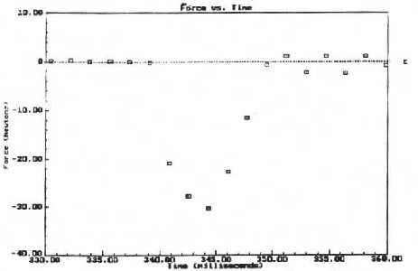
Procedure 7, d), Finally, you need the following sample to determine where the collision begins and ends.
Procedure 8
Compare the "momentum change" with the measured "Impulse".
Hint: First, what is your theoretical prediction? Second, what is your experimental integral?
Do they agree with each other? If not, what are the sources of errors?
How many percent does each of them cause?
Be ware that this is how you answer Question 10-1 on page 33.
Procedure 10
Question 10-1 on page 33: (0.5 points, the theoretical prediction,
and 0.5 points, your experimental verification)
How accurately does your measured impulse agree with the change in momentum?
Hint: If you do the requirement in Procedure 8 with my given hint,
then you do not have to answer this question, in fact.
Also, you can use AE10-2 and AQ10-3 to answer Q10-1.
AE10-2 is the method to analyze friction, which is one of the sources of errors.
And AQ10-3 is how we predict the percentage error due to an inclined track before our experiment.
Additional Example 10-2: (You do not have to answer.)
Consider m k is the coefficient of kinetic friction between the glider and the track. The track is unlike the practice question, perfectly leveled. Since now friction is the only force along the track, we can apply 2nd law to determine the acceleration m kmg=fk=m|a|. You can still measure t1, t2, and L. In addition, we also need to measure the distance between the photogate and the deflecting bar, say D. How can you figure out D p in terms of m, t1, t2, L, D, and m k?
Please recall that v1 and v2 are the velocities right before and after the collision.
In fact, you also can use AE10-2 to answer Q10-1 because AE10-2 is the method to analyze friction, which is one of the sources of errors.
Additional Question 10-3:
D is the distance from the photo-gate to the force transducer.
In the given hint of Q10-1, I ask: "What are the sources of errors?
How many percent does each of them cause?" Now, because of the above formula,
we know how to predict the possible percentage error caused by an inclined plane.
Assume q @ sinq = (0.10 cm/100.0cm) = 1.0´ 10-3(rad).
Plug in your measured t1, t2, L, D, and sinq.
Compare your result DPinclined with your theoretical DP in procedure 6.
Outline for Newton's Second Law _Part (II)
Courtesy of Benli Young
Procedure 1, a) Prepare and weigh the gliders and all masses
|
Item |
Mass, Unit:( ) |
|
Hanger |
|
|
Glider |
|
|
The greatest mass |
|
|
The medium mass |
|
|
Small Weights |
|
|
|
|
|
Chrome Weights |
|
|
|
|
Glider length, L = _________________
Procedure 5, b) iv, Calculate the calibration force, mag = _________________ for 0.5 point, Unit:( ) for 0.5 point, with your work of sample calculation for 1 point.
.
Procedure 6, b) iii, Print a good oscilloscope graph out (the trace of the force voltage vs. time).
Procedure 6, c) ii & iii
Record the time and calculate the velocities:
(Velocity = glider length / time)
Notice: the positive velocities and forces are measured to the left.
Theoretical Momentum Change ΔP= Pf _ Pi =m( vf _ vi )
Total glider mass used in the collision = ______________
|
|
Time, UNIT: ( ) |
Velocity, UNIT: ( ) |
Momentum, UNIT: ( ) |
|
Before collision, t1 |
|
|
|
|
After collision, t2 |
|
|
|
Theoretical Momentum Change, ΔP= _______________
Procedure 7, e) Record the experimental results of the integration.
Procedure 7, f) Print out only one Graph "Force vs. Time".
Procedure 8, Compare the “momentum change” with the measured “Impulse”.
Hint: First, what is your theoretical prediction? Second, what is your experimental calculation? Do they agree with each other? If not, what are the sources of errors? How many percent does each of them cause? Be ware that this is how you answer Question 10-1 on page 33.
Procedure 9, Repeat the experiment with adding weights to the glider: (Don't print out any graph here.)
|
|
1 |
2 |
|
Total glider mass |
|
|
|
Momentum change, P |
|
|
|
Impulse Fdt |
|
|
|
% error |
|
|
Procedure 10,
Answer Question 10-1.
Remark:
We use two unit systems in physics, SI unit system, or so-called MKS system, and CGS unit system.
“MKS” means “meter”, “kilogram”, and “second.” Hence, the SI unit of force is exactly kg-m/sec2. We call it “Newton.”
“CGS” means “cm”, “gram”, and “second.” Therefore, the CGS unit of force would have to be g-cm/sec2. People use to call it “dyne.”
|
Lab 4 of 40A|
Main Menu Page|
Lab 6 of 40A|
My Home Page
