WATCH OUT: This step is not as simple as the previous one,
You really need a lot of caution and ability with the soldering iron.
We now will retouch a little the local oscillator, in order to able to improve tuning of the
frequencies above 900 mhz, for which the receiver was not adjusted in the factory.
The tuning circuits are inside the metal box next to the antenna plug, manufactured by SHARP.
Inside here there are two oscillators, for the UHF and VHF. We will adjust a link in the UHF circuit,
to enable it to work on slightly higher frequencies.
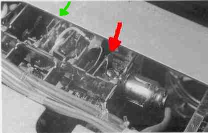
1) Open the lid on the metal box. Inside there's the circuit in the following figure.
 2) Tune the FRG on 460 Mhz.
On the PLL unit, below the IC MC 145158, you can see the pin marked TP02.
With a digital tester measure the voltage on this TP02, it should be around 1,1-1,5 V.
The PLL unit is, among the two high printed circuits, the one closer to our metal box,
next to it there's written 'PLL UNIT'.
3) On the figure, next to the red arrow, there's a horizontal copper strip, with another
vertical copper strip strip soldered at its end. These two strips make an angle of 90°.
With a very fine tipped soldering iron melt the soldering which connects these two strips,
and bend the vertical strip a bit towards the beginning of the horizontal strip,
to shorten a bit this loop.
A fraction of a millimeter (about 0,5 mm) should be enough.
Measure again the voltage on TP02, receiver tuned on 460 Mhz.
The voltage should be now around 0,6 V.
If not, you can still make small adjustments to the copper link.
Now, with the FRG tuned on 950 Mhz, you should have a voltage on TP02 of about 30,5 V.
4) Now, let's improve the reception sensibility in this high band.
Connect the digital tester on pin nr. 12 of the IC MC3357, the FM discriminator.
The voltage should vary from about 0,6 V with no signal received, to about 1,2 V with maximum
signal, with the squelch unblocked.
Tune the receiver to a frequency around 460 mhz, which has to be busy with some signal.
(A repeater output would do fine)
Next to the green arrow in above figure there are some pairs of copper strips, which make
some resonating links. With a little NON INDUCTIVE screwdriver adjust these strips a little closer
or farther from each other, until you read the maximum value on the tester, always whlie receiving
the same signal.
Repeat this step also on higher frequencies, the corrections on the copper links must be very fine.
Now the reception on 900 and more mhz should be much better.
WARNING: DO NOT ATTEMPT TO DO THIS IF YOU DO NOT
FEEL CONFIDENT WHEN USING SOLDERING EQUIPMENT.
DO NOT BLAME ME IF YOU SCREW UP YOUR RECEIVER OR
DO ANY DAMAGE TO ANYTHING YOU ARE USING.
Go Back
2) Tune the FRG on 460 Mhz.
On the PLL unit, below the IC MC 145158, you can see the pin marked TP02.
With a digital tester measure the voltage on this TP02, it should be around 1,1-1,5 V.
The PLL unit is, among the two high printed circuits, the one closer to our metal box,
next to it there's written 'PLL UNIT'.
3) On the figure, next to the red arrow, there's a horizontal copper strip, with another
vertical copper strip strip soldered at its end. These two strips make an angle of 90°.
With a very fine tipped soldering iron melt the soldering which connects these two strips,
and bend the vertical strip a bit towards the beginning of the horizontal strip,
to shorten a bit this loop.
A fraction of a millimeter (about 0,5 mm) should be enough.
Measure again the voltage on TP02, receiver tuned on 460 Mhz.
The voltage should be now around 0,6 V.
If not, you can still make small adjustments to the copper link.
Now, with the FRG tuned on 950 Mhz, you should have a voltage on TP02 of about 30,5 V.
4) Now, let's improve the reception sensibility in this high band.
Connect the digital tester on pin nr. 12 of the IC MC3357, the FM discriminator.
The voltage should vary from about 0,6 V with no signal received, to about 1,2 V with maximum
signal, with the squelch unblocked.
Tune the receiver to a frequency around 460 mhz, which has to be busy with some signal.
(A repeater output would do fine)
Next to the green arrow in above figure there are some pairs of copper strips, which make
some resonating links. With a little NON INDUCTIVE screwdriver adjust these strips a little closer
or farther from each other, until you read the maximum value on the tester, always whlie receiving
the same signal.
Repeat this step also on higher frequencies, the corrections on the copper links must be very fine.
Now the reception on 900 and more mhz should be much better.
WARNING: DO NOT ATTEMPT TO DO THIS IF YOU DO NOT
FEEL CONFIDENT WHEN USING SOLDERING EQUIPMENT.
DO NOT BLAME ME IF YOU SCREW UP YOUR RECEIVER OR
DO ANY DAMAGE TO ANYTHING YOU ARE USING.
Go Back