HOW TO EXPAND THE FREQUENCY RANGE OF THE
FRG9600 FROM 60-905 MHZ TO 20-950 MHZ
WARNING: DO NOT ATTEMPT TO DO THIS IF YOU DO NOT
FEEL CONFIDENT WHEN USING SOLDERING EQUIPMENT.
DO NOT BLAME ME IF YOU SCREW UP YOUR RECEIVER OR
DO ANY DAMAGE TO ANYTHING YOU ARE USING.
First write down all the stored frequencies, in case the memories of the
receiver get lost. Then turn it off and disconnect all cables.
I will not explain how to open the case. If you can't find it out by
yourself, you sure won't be able to do the work.
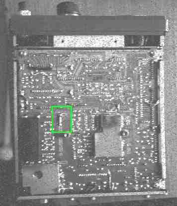
What you see above, is the Printed Circuit Board (PCB) of the FRG9600,
seen from the bottom.
What you need: 1 resistor 1 KOhm 1/4 or 1/2 Watt, 3 pieces of wire,
soldering iron
GREEN SQUARE: This is the 1 KOhm resistor, soldered between the pin # 1
(Counting from the top) and the nearby ground terminal of the pin array
marked J8001/J9001, next to the black rubber piece.
Beware, the the sensitivity is not very good in the expanded
frequency range, but it is still usable. Also interference from
the computer might matter. I've also noticed that some receivers
might be better, others might be less good, depending on how the
front-end is aligned. I'm working on this, so stay tuned :-).
Now turn around the opened FRG9600, so that you can look inside from the
top.
Locate the BAND UNIT. This is the vertical circuit board with a metal
frame, closest to the front panel. Next to it, on the main Circuit Board,
there is the text BAND UNIT written. You have to solder the 3 jumper
wires on this Band Unit.
When you look at the front of the Band Unit, near its top, you will see
6 empty holes, marked on the below drawing with x.
(Top)
------------------------------------
| |
| x.......x x.......x |
| _ x.......x |
| |S| |
| |0| |
| |1| |
You have to solder the jumpers marked x.....x, either by connecting the
soldering points on the back, or inserting the jumpers through the holes
on the front.
If you have the switch S01 inserted, this must be on the OFF position.
Usually this switch is not installed, its use is to limit the frequency
range of the FRG, probably for some countries who required it.
Now check your solderings. They must be clean, and must not touch the
nearby pins. Check also that you have not left any metal chips from
the jumpers or the soldering lead inside the receiver. Close the box,
connect the cables and turn it on.
With the dial you can now select all frequencies between 0.0000 and
999.0000 Mhz, but only the range 20.0000 - 950.0000 will be operational.
WARNING: On some frg's the frequency on the display is off
by 27.250 Mhz from the real frequency you are receiving on
the low band, i.e. if you want to listen to 50.000 Mhz you
have to enter 22.750 Mhz.
And now, let's improve a little the reception above 900 Mhz.
Back to the HOMEPAGE