ELECTRICAL CALCULATION SOFTWARE
VOLTAGE DROP & CABLE SIZING PROGRAM
(OVERVIEW)
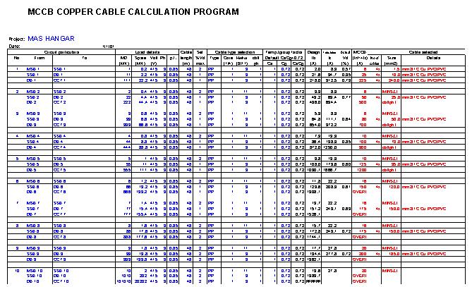
THE OVERALL PROGRAM VIEW
-
The column shall be indicate the name of the Board of the
outgoing cable that need to calculate the voltage drop
-
The column shall be indicate the name of the board connected
to the cable that need to calculate the voltage drop
-
Maximum demand or
the desired power in kW.
-
Enter the desired
spare power particularly used for sizing the incoming breaker where usually
sized for 1.2 times the maximum demand current or if any spare capacity is
required.
The total power used for the calculation will be the MD power + spare kW.
-
The voltage that supplied to the system / circuit (currently
this software only support 415V)
-
The system current supply (currently this software only
support three phase). So enter �3� in this column.
-
The system power factor as Authorities provider (default
0.85)
-
For generator set supply shall be 0.8
-
The distance (in meter) from the incoming board to outgoing
board
-
Set the desired
limit of maximum voltage drop for the cable in percentage.
-
The set of voltage drop (the whole system shall be not more
than 4% for the particular circuit
-
Construction of cable to be used
-
Cu - Copper
-
PVC - PVC cable
PP - PVC/PVC cable
PSP - PVC/SWA/PVC cable
XLP - XLPE/PVC cable
XSP - XLPE/SWA/PVC cable
-
PVC cable - Can
be installed in enclosed conduit/trunking (Method 3) or on tray (Method 11).
Available in single core:
a)
For enclosed minimum 1.5mm2 up to 630mm2.
b)
For on tray minimum 25mm2 up to 1000mm2.
-
PVC/PVC Cable -
Can be installed in enclosed conduit/trunking (Method 3) or on tray (Method 11).
Available in single core:
a)
For enclosed minimum 1.5mm2 up to 630mm2.
b)
For on tray minimum 25mm2 up to 1000mm2.
-
PVC/SWA/PVC Cable
- Limited to install on tray/ladder only ((Method 11).
Available in:
a)
Single core from 50mm2 to 1000mm2.
b)
Four-core from 1.5mm2 to 400mm2.
-
XLPE/PVC Cable -
Can be installed in enclosed conduit/trunking (Method 3) or on tray (Method 11).
Available in single core:
a)
For enclosed minimum 1.5mm2 up to 630mm2.
b)
For on tray minimum 25mm2 up to 1000mm2.
-
XLPE/SWA/PVC
Cable - Limited to install on tray/ladder only (Method 11).
Available in:
a)
Single core from 50mm2 to 1000mm2.
b)
Fourr-core from 1.5mm2 to 400mm2.
-
Nos of cable core
to be indicated under column CORE (1/4). Enter 1 for single-core, enter 4 for
four-core.
-
1C for single
core and 4C for four-core.
-
The way that the
cable to be installed / laid.
-
a)
Enter 3 for enclosed installation, such as in GI conduit/trunking.
b) Enter 11 for installation on
tray/ladder flat touching or trefoil.
-
To indicate cable per phase
-
a)
For single-core cable:
e.g. 1 = 1 cable per phase (total 4 cables)
2 = 2 cables per phase (total 8 cables)
b) For four-core cable:
e.g. 1 = 1 No. 4-core cable
3 = 3 No. 4-core cables
-
The factor in the BS standard that considering as follows: -
a.
Cg
- Grouping derating
factor
b.
Ca
- Ambient temperature
derating factor.
-
If both Ca and Cg
are not entered, then the default derating factor is 0.72
-
Design Ib � Design or maximum demand current in ampere.
-
Tabulated It - Required tabulated current-carrying capacity in ampere.
-
Ita - Actual
tabulated current-carrying capacity (or the current rating of the cable at 30oC).
-
Iz - Effective
current-capacity capacity under the prescribed method of installation (Ita x C).
-
The actual
voltage drop for the selected cable in percentage of 415V.
-
Max mV/A/m
allowed - The mV/A/m of the
selected cable shall be less than the max mV/A/m allowed so that the calculated
voltage drop will be less than the set %Vd max.
-
In - Circuit
breaker current rating in ampere.
-
MCCB - Moulded
Case Circuit Breaker manimum size 6A up to 1200A.
(Non IEC ratings are also available).
-
The programmed will provide automatically the cable size,
nos. of cable and method of installation for the calculated circuit to suit the
voltage drop set.
-
a)
This program is only applicable to three-phase calculation.
b) Enter data in blue colour areas.
c) Black colour areas are control
parameters.
d) Red colour areas are the
selected MCCB rating, number and size of selected cables.
-
a)
For overload protection: In >= Ib,
In =< Iz, Ib =< Iz.
b) For
short-circuit protection: In > Iz
c) For normal application, ie
overload with short-circuit protection,
use It = In/C.
d) For motor feeder circuit, where
MCCB is usually larger to allow for starting current.
Then use It = Ib/C.
Additional overload protection device is required.
If the result shows as follows DO as recommended
-
Re-inspect the
data entry OR entered wrong cable type.
-
The load current
is too small for the minimun cable size to carry.
This applies particularly to single core cable.
Try to use 4 core cable instead.
-
a) For MCCB
- exceeded the largest MCCB is 1200A.
b) For CABLE - exceeded the largest cable rated current
- Increase the number of cable per phase.
Link to Other Calculation
1. Voltage Drop & Cable Sizing
2. Capacitor Bank Calculation 1
3. Capacitor Bank Calculation 2
6. Motor MCCB Selection Calculation
7. Street Lighting Voltage Drop
8. MATV Signal Strength Calculation
9. SAT Signal Strength Calculation
HOME -- FREE DOWNLOAD -- SITEMAP