 |
|
|
|
|
|
|
|
|
|
|
|
|
|
|
|
|
|
|
|
|
|
| GE (RCA) SR-III Radio |
|
|
Next Home |
|
|
|
|
A Hot Rod Project |
|
|
|
I have been thinking about this project for quite a while. The reason I finally started it is because I finally found some nice metal cases in which to assemble it. The original inspiration was because I have always had a lot of favor for this radio. It's inexpensive, usually about $50.00 US, but it isn't cheap. It is well designed with moderately high quality components, has a decent RF amplifier stage, decent filter selection from very wide for good AM fidelity, to a well-selected narrower filter for serious DX listening. Basically, its sensitivity and selectivity are about as good as anyone has accomplished for the price - dare I say four times the price. It has a good FM section, too, but that has nothing to do with my intents and purposes. It has an impressive 2-way speaker system which uses basic faux-technology (read, computer speaker techniques) to make it sound BIG, not true high fidelity, but none-the-less, quite pleasant for a plastic-cased portable radio. Another reason I wanted to do this is because several of our ham club members are broadcast station engineers, and one friend is a well-known DJ. All these guys seem to have an SR-III kicking around in their equipment vans to use for "off-air" sound checks, especially when doing remote broadcasts. Since innovation is always easier than invention (usually), I figured it was time for me to have some fun. So these next few pages will take us step-by-step through my "Super Superadio-III" (SSR-III) project as they happen. Please be patient and check back every week - I'll post the progress as it occurs. |
|
|
|
 |
|
|
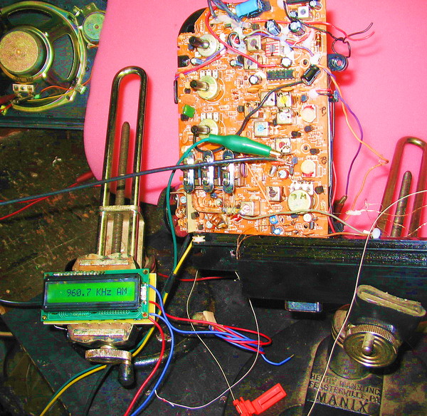
The first tep was to gut the monster and wire in an AADE digital frequency display. I note with glee that dreaded dial cord and orange indicator lying limp on my work bench. These radios are notoriously badly out of calibration when purchased. I aligned mine when I first got it, and will post the procedure later in this project - for those who are happy with their SR-III as purchased, but want to "fix" the frequency alignment.
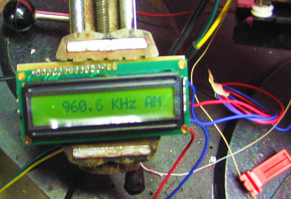
Here is the DFD tacked into the circuit with the signal coming from the center pin of Q15 wired across the varactor tuning diode. it is buffered with a 7 to 12pF ceramic cap to reduce loading the tuning oscillator. |
|
|
|
|
|
|
 |
|
|
|
Not visible here is a 2 watt rheostat that controls the display's back-lit LEDs from zero to 150mA. Notice that having PC board vices are almost mandatory if you are going to work on this project.
Ahhh, there's another photo of that rediculous, evil orange indicator. With all due respect, I'll give it a proper funeral.
Actually, I'm really not that sinister - have another SR-III at the office that I'll leave stock/standard - out of respect.. |
|
|
|
|
|
 |
|
|
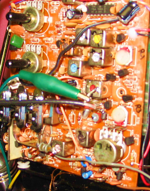
Here are the connection points. Disregard the green clip lead which is being used to monitor voltage levels. The actual oscillator signal comes from the RG-174 coax which is tacked to the capacitor feeding the collector of Q15. Ground is borrowed from the top of the IF can. If you look very closely, you can make out the 7pF coupling cap.
On the lower right of the photo is the tuning pot. Note that I marked the legs "H" and "L" to indicate the up and down frequency directions of the pot's wiper for future convenience.
The pot rotates through 312 degrees. that is much too fast for tuning the full band. The original dial string and pulley arrangement provided a ratio reduction of about 8:1. I am going to use a 12 position rotary switch for the 12, 100kHz segments of the AM broadcast band, and a "fine tune" pot which will allow the actual tuning of everything within that particular segment. It will appear to function as a Wadley-loop type radio. |
|
|
|
|
|
Sept 26, 2006 |
|
|
|
|
|

|
|
|
|
|